Home > Hardware > Extreme Device Pin Assignments

|
Extreme Device Pin Assignments
Read about Extreme Networks device Console and Ethernet port pin assignments in this topic, including standard and PoE (power over Ethernet) pin assignments.
The following sections provide detailed pin-assignment information for Extreme Networks devices.
The illustrations and tables below describe pin assignment and wiring information for standard RJ45 and Micro USB Console ports for Extreme Networks devices.
RJ45 Console Port
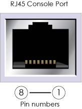
| Pin | Definition | Pin | Definition |
|---|---|---|---|
| 1 | NC | 5 | Signal GND |
| 2 | NC | 6 | RXD (input) |
| 3 | TXD (output) | 7 | NC |
| 4 | Signal GND | 8 | NC |
Micro USB Console Port
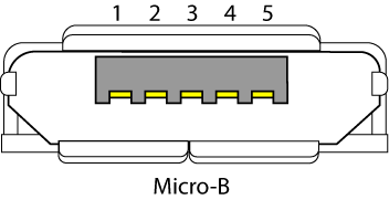
| Pin | Name | Color | Definition |
|---|---|---|---|
| 1 | VCC | Red | +5 VDC |
| 2 | D- | White |
Data - |
| 3 | D+ | Green | Data+ |
| 4 | ID | Dark Blue | Mode detect. May be N/C, GND, or an attached device presence indicator (shorted to GND with resistor) |
| 5 | Signal GND | Black | Ground |
Ethernet Port Pin Assignments
Standard Ethernet Port Pin Assignments
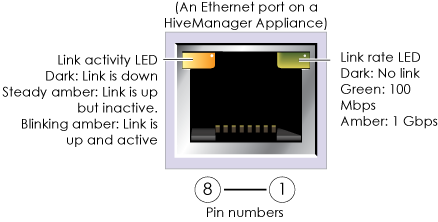
This section contains pin assignment and wiring information for standard and PoE (power over Ethernet) Ethernet ports for Extreme Networks devices. This illustration shows a non-PoE Ethernet port on a ExtremeCloud IQ Appliance. The table following the illustration describes the pin assignments for non-PoE ports.
|
Pin |
10/100Base-T Data Signal |
1000Base-T Data Signal |
|---|---|---|
|
1 |
Transmit + |
BI_DA+ |
|
2 |
Transmit - |
BI_DA- |
|
3 |
Receive + |
BI_DB+ |
| 4 | (unused) | BI_DC+ |
| 5 | (unused) | BI_DC- |
| 6 | Receive - | BI_DB- |
| 7 | (unused) | BI_DD+ |
| 8 | (unused) | BI_DD- |
| Legend: BI_D = bidirectional, A+/A-, B+/B-, C+/C-, D+/D- = wire pairing | ||
Power over Ethernet Port Pin Assignments
The pin assignments for PoE Ethernet ports follow the TIA/EIA-568-B standard. The ports accept standard cat3, cat5, cat5e, or cat6 Ethernet cable and can receive power from power-sourcing equipment (PSE) that is 802.3af-compatible. If you use cat5, cat5e, or cat6 cables, Extreme Networks PoE devices can also support 802.3at-compliant PSE. Such equipment can be embeded in a switch or router, or it can come from purpose-built devices that inject power into the Ethernet line en route to the device. Because PoE ports have autosensing capabilities, the wiring termination in the Ethernet cable can be either straight-through or crossover.
The following table describes the pin assignments for PoE Ethernet ports.
| 802.3af Alternative A (data and power on the same wires) | 802.3af Alternative B (data and power on separate wires) | 802.3af wiring options | ||||||
|---|---|---|---|---|---|---|---|---|
| Pin | Data Signal | MDI | MDI-X | MDI or MDI-X | 1 | 2 | 3 | 4 |
| 1 | Transmit + | DC+ | DC- | --- | DC1+ | DC1- | DC1+ | DC1- |
| 2 | Transmit - | DC+ | DC- | --- | DC1+ | DC1- | DC1+ | DC1- |
| 3 | Receive + | DC- | DC+ | --- | DC1- | DC1+ | DC1- | DC1+ |
| 4 | (unused) | --- | --- | DC+ | DC2+ | DC2+ | DC2- | DC2- |
| 5 | (unused) | --- | --- | DC+ | DC2+ | DC2+ | DC2- | DC2- |
| 6 | Receive - | DC- | DC+ | --- | DC1- | DC1+ | DC1- | DC1+ |
| 7 | (unused) | --- | --- | DC- | DC2- | DC2- | DC2+ | DC2+ |
| 8 | (unused) | --- | --- | DC- | DC2- | DC2- | DC2+ | DC2+ |
| Legend: MDI = Medium-dependent interface for straight through connections | ||||||||
PoE ports are auto-sensing and can automatically adjust to transmit and received data over straight-through or crossover Ethernet connections. Likewise, they can automatically adjust to 802.3af Alternative A and B power delivery methods. Furthermore, when the Alternative A method is used, the ports automatically allow for polarity reversals depending on their role as either MDI or MDI-X. In 802.3at, the 1/2 and 3/6 wire pairs connect to DC source 1 and the 4/5 and 7/8 pairs to CD source 2 in PSE. Although the exact polarity depends on the PSE design, the Ethernet ports can support all possible options.
T568A and T568B are two standard wiring termination schemes. The only difference between them is that the white/green + solid green pair of wires and the white/orange + solid orange pair of wires are reversed.
For straight-through Ethernet cables - using either the T568A or T568B standard - the eight wires terminate at the same pins on each end.
For crossover Ethernet cables, the wires terminate at one end according to the T568A standard and at the other end according to the T568B standard.
Smart PoE
The AP320, AP340, AP350, AP250, AP370, AP390, BR200WP, SR2024P, SR2124P, and SR2124P apply the Extreme Networks concept of smart PoE to adjust power consumption as necessitated by varying levels of available power. The AP340 and BR200WP support PoE on the ETH0 and ETH1 interfaces and can draw power through either on or through both simultaneously. The SR2024P supports PoE power on Ethernet ports 1 through 8, and the SR2124P supports PoE power on all 24 ports. The SR2208P supports PoE on 8 Ethernet ports. The SR2224P and SR2324P support a combination of PoE and PoE+ on all 24 ports.
Based on the available power that the device detects, it manages internal power use by making the following adjustments:
No adjustments are needed when the power level is 20 W (watts) or higher. If the available power drops to a range between 18 and 20 W, the device disables its ETH1 interface, assuming that it is drawing power through its ETH0 interface. If it is drawing power solely through its ETH1 interface, then it disables its ETH0 interface instead.
If the power level drops to the 15 – 18 W range, the device then switches from 3x3 MIMO to 2x3 MIMO.
In rare cases when the power drops between 13.6 and 15 W and further power conservation is necessary, the device reduces the speed on its active Ethernet interface—ETH0 or ETH1—from 10/100/1000 Mbps to 10/100 Mbps.
Finally, in the event that there is a problem with the PoE switch or Ethernet cable and the power falls between 0 and 13.6 W, the device disables its wireless interfaces and returns its ETH0 and ETH1 interfaces to 10/100/1000 Mbps speeds.
Through the application of smart PoE, the device can make power usage adjustments so that it can continue functioning even when the available power level drops.
Copyright © 2020 Extreme Networks. All rights reserved. Published March 2020.