Home > Hardware > ap > AP460C, AP460S6C, and AP460S12C Hardware User Guide

|
AP460C, AP460S6C, and AP460S12C Hardware User Guide
Install and view specifications and compliance information for AP460C , AP460S6C, and AP460S12C devices.
AP460C, , AP460S6C, and AP460S12C devices are Tri Radio 802.11ax access points based on advanced radio technology and IP67 rated for harsh and extreme outdoor environments, with an extended temperature range (-40 C - +60 C). The tri-radio design delivers 802.11ax 2x2:2 and 4x4:4 data rates concurrently on the 2.4 and 5 GHz radios, with a third radio as a dedicated dual-band sensor.
For more information about Extreme Networks APs and products in general, see Introduction to Extreme APs.
For regulatory and compliance information, see "Regulatory Compliance Statements".
Important! Change the Country Code
If your access point is configured for the World Regulatory Domain, it is important to set the country code to the country in which the AP will be deployed to meet regulatory requirements and for optimal wireless operation. To do this, follow these steps:

Note
The country code selection is for World models only and is not available to FCC, CAN, and other country-specific models. Per FCC regulations, all Wi-Fi products marketed in the United States must be set to U.S. channels only.Safety Guidelines
The information in this section applies to AP460C, AP460S6C, and AP460S12Cdevices.
The following safety icons are used in these guidelines to identify the type of precaution:

|
This icon indicates a general caution. Failure to comply with a caution notification can result in damage to equipment. |

|
This icon indicates an electrical caution. Failure to comply with an electrical notification can result in serious injury or death, and extensive damage to equipment. |

|
This icon indicates a laser caution. Failure to comply with a laser caution can result in serious injury. |
| The following table lists the safety precautions you should follow when installing your AP460C, AP460S6C, and AP460S12Cdevices. | |
|
|
Extreme Networks devices must be installed by a professional installer who is certified to install these types of devices and to ensure that they are properly grounded and meet applicable local and national electrical codes. |
|
|
These devices are intended for indoor use only. |
|
|
Warning: This is a Class A product. In a domestic environment this product may cause radio interference in which case the user may be required to take adequate measures. |
|
|
Do not install the device in an environment where the operating ambient temperature might exceed the recommended ranges. |
|
|
For products available in the USA/Canada market, for the 2.4 GHz band, only channels 1-11 can be operated. Selection of other channels is not possible. |
|
|
Changes or modifications made to this device that are not expressly approved by the party responsible for compliance could void the user's authority to operate the equipment. |
|
|
Use only attachments and accessories specified by Extreme Networks. |
|
|
These devices are not intended for use by persons (including children) with reduced physical, sensory, or mental capabilities, or with lack of experience of knowledge unless they are given supervision or instruction concerning use of the devices by a person who is responsible for their safety. Children should be supervised to ensure that they do not play with the devices. |
|
|
Electrostatic discharge (ESD) can damage equipment and impair electrical circuitry. ESD damage occurs when electronic components are improperly handled and can result in complete or intermittent failures. Be sure to follow ESD-prevention procedures when handling electronic components and equipment. |
|
|
During operation, the surfaces of AP460C, AP460S6C, and AP460S12C can become hot. Use caution when handling. |
|
|
To meet federal radiation exposure requirements, these devices should be installed at a minimum distance of 12" (30 cm) from people or animals. |
The following sections describe how to mount your AP in an outdoor location on a pole or flat surface.
Shipping Carton Contents
The AP460C, AP460S6C, and AP460S12C shipping carton contains the following items:
Install the AP
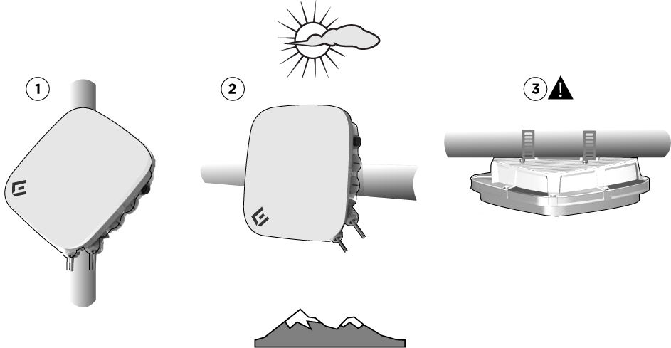
Mount the AP460C, AP460S6C, or AP460S12C horizontally or vertically on a pole using the built-in brackets on the hardware, or on a solid flat surface using an accessory bracket (see "Accessories "). These devices can be installed in even the most extreme outdoor environments. The following sections describe the installation process.
Before you install the device, make sure that you have all the materials and tools necessary, and familiarize yourself with the safety and site hazard warnings.
Note
For best performance, deploy devices in relatively open areas at least 100' (30.5 m) apart from each other.Required Tools
To install your device horizontally or vertically on a pole, you will need the following items:
Installation Methods
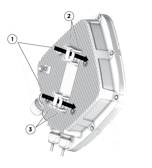
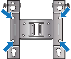
Install the Device on a Vertical or Horizontal Pole
Use the following steps to install the device on a vertical or horizontal pole.
Install the Device on a Flat Surface
You can Install the device on a vertical or horizontal solid flat surface using the accessory wall bracket (AH-ACC-BKT-ASM). This kit contains the mounting bracket and four bolts without washers in the plastic bag labeled "Wall Mount". You will need to provide four mounting bolts or screws and wall mount anchors that are appropriate for the wall type where you are installing the device.
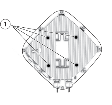
Note
If you are not installing the device on a concrete wall, you can use threaded screws and screw-in wall anchors (not supplied) to mount the device. 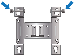
For horizontal mounts, be sure that the ports are facing earth to reduce the chance of water entering the chassis. As an added security measure, you can thread a safety strap through one of the cable strap slots in addition to the hose strap. Connect the other end of the strap to a secure object.
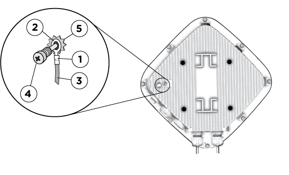
Ground the Device
Use the following steps to properly ground the AP.
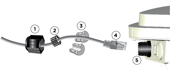
Install the Waterproof Ethernet Cable Housing
Use the waterproof Ethernet cable housing to ensure a weatherproof seal for the Ethernet cable. Use the following procedures to install the housing.
Accessories
The following accessories are available for the AP460C, AP460S6C, and AP460S12C:
Remove the RJ45 Cable Safely
If you need to uninstall the device for any reason, for example for troubleshooting, you will need to remove the RJ45 cable. Use the following steps:
 Make sure not to touch any components of the PCBA board near the gland area.
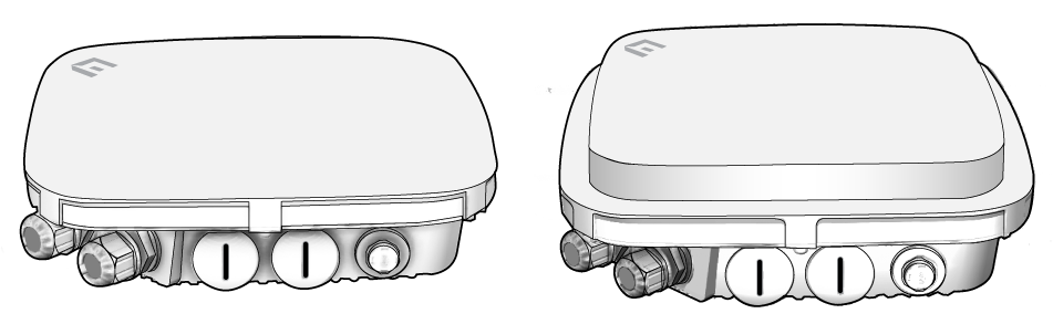
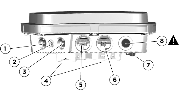
You can see the hardware components in the illustration below and read about them in the sections that follow. The components are identified below by number:
1. Eth0 PoE+
2. Status light
3. Eth1
4. Built-in mounting brackets
5. USB port
6. Mirco USB Console port and Reset button
7. Ground
8. Air pressure valve. DO NOT REMOVE.
Status Light
The status light, located between the two Ethernet ports, conveys operational states for system power, firmware updates, Ethernet and wireless interface activity, and major alarms. At setup, this light cycles through the following sequence:
Ethernet Ports
These devices have two RJ45 Ethernet ports (Eth0 and Eth1) that automatically negotiate half- and full-duplex connections with the connecting device. The ports are autosensing and adjust to straight-through and crossover standard Cat2, Cat5, Cat5e, or Cat6 Ethernet cables automatically. The AP receives power through an Ethernet connection to the ETH0 port from PSE (power sourcing equipment) that is compatible with the 802.3at and 802.3at standards.
Micro USB Console Port
This illustration above shows the USB (5) , Micro USB Console port and Reset button (6), which are located behind waterproof screw caps.
Remove the waterproof screw cap to access the micro USB port and the Reset button. Through the micro USB Console port you can make a serial connection between your management system and the AP. When you connect to the device using the micro USB Console port, the management station from which you connect to the device must have a VT100 emulation program, such as Tera Term Pro© (a free terminal emulator) or Hilgraeve HyperTerminal® (provided with Windows® operating systems from XP forward). The serial connection settings are: 9600 bits per second, 8 data bits, no parity, 1 stop bit, no flow control.
You can order a micro USB console adapter cable here.
Note
To troubleshoot these devices, you must first uninstall it from the outdoor location.The pin-to-signal mapping for the Console port is shown below:
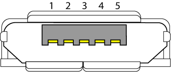
| Pin | Definition |
|---|---|
| 1 | NC |
| 2 | RxD (input to AP) |
| 3 | TxD (output to terminal) |
| 4 | Signal (GND) |
| 5 | Signal (GND) |
USB Port
These devices have a standard USB port that you can use to connect USB-based beacons (iBeacon, for example) and IoT (Internet of Things) devices. To access the port, remove the gland cap screw.
Reset Button
The Reset button is located behind the same waterproof screw cap as the micro USB port. Use the Reset button to reset the device or restore the factory default settings.
To prevent the reset button from resetting the configuration, enter this command:
no reset-button reset-config-enable
When this command is enabled, pressing the button for 5 seconds will still reboot the AP, but pressing it for more than 10 seconds will not reset its configuration.
The following sections list radio, device, power, and environmental specifications for these devices.
Interfaces
Radios
Radio Specifications
802.11a
802.11b
802.11g
802.11n
2.4-2.48 and 5.150-5.350, 5.470 - 5.850 GHz operating frequency
802.11ac
802.11ax
802.11ax (for 5 GHz sensor)
2.4-2.48, 5.150-5.350, 5.470 - 5.850 GHz operating frequency
Transmit Power and Sensitivity Specifications
Note
Output power may be limited by regulatory requirements.2.4 G: Tolerance +2/-2 dB @25°C
| Mode | Data Rate | Power | Unit |
|---|---|---|---|
| 11b | 1,2,5.5,11 | 18 | dBm |
| 11g | 54 Mbps | 15 | dBm |
| 48 Mbps | 16 | dBm | |
| 36 Mbps | 17 | dBm | |
| 6 Mbps | 18 | dBm | |
| HE20 | MCS 0,1,2 | 18 | dBm |
| MCS 3 | 17 | dBm | |
| MCS 4, 5 | 16 | dBm | |
| MCS 6,7 | 15 | dBm | |
| MCS 8,9 | 14 | dBm | |
| MCS 10,11 | 12 | dBm | |
| 2.4 G Sensitivity | |||
| 11b | 1 Mbps | -99 | dB |
| 11 Mbps | -90 | dB | |
| 11g | 6 Mpbs | -96 | dB |
| 36 Mpbs | -84 | dB | |
| 48 Mbps | -80 | dB | |
| 54 Mbps | -78 | dB | |
| HE20 | MCS 0 | -95 | dB |
| MCS 1 | -91 | dB | |
| MCS 2 | -89 | dB | |
| MCS 3 | -86 | dB | |
| MCS 4 | -83 | dB | |
| MCS 5 | -79 | dB | |
| MCS 6 | -77 | dB | |
| MCS 7 | -76 | dB | |
| MCS 8 | -72 | dB | |
| MCS 9 | -70 | dB | |
| MCS 10 | -67 | dB | |
| MCS 11 | -64 | dB |
5 G:
Tolerance +2/-2 dB @25°C
| Mode | Data Rate | Power | Unit |
|---|---|---|---|
| 11a | 54 Mbps | 18 | dBm |
| 48 Mbps | 18 | dBm | |
| 36 Mbps | 19 | dBm | |
| 6 Mbps | 20 | dBm | |
| HE20 | MCS 0,1,2 | 20 | dBm |
| MCS 3,4 | 19 | dBm | |
| MCS 5,6 | 18 | dBm | |
| MCS 7,8 | 17 | dBm | |
| MCS 9 | 16 | dBm | |
| MCS 10 | 15 | dBm | |
| MCS 11 | 14 | dBm | |
| HE40 | MCS 0,1,2 | 19 | dBm |
| MCS 3,4,5 | 18 | dBm | |
| MCS 6,7,8 | 17 | dBm | |
| MCS 9 | 16 | dBm | |
| MCS 10 | 15 | dBm | |
| MCS 11 | 14 | dBm | |
| HE80 | MCS 0,1,2 | 19 | dBm |
| MCS 3,4,5 | 18 | dBm | |
| MCS 6,7,8 | 17 | dBm | |
| MCS 9 | 16 | dBm | |
| MCS 10 | 15 | dBm | |
| MCS 11 | 14 | dBm | |
| HE160 | MCS 0,1,2 | 19 | dBm |
| MCS 3,4,5 | 18 | dBm | |
| MCS 6,7,8 | 17 | dBm | |
| MCS 9 | 16 | dBm | |
| MCS 10 | 15 | dBm | |
| MCS 11 | 14 | dBm | |
| 5 G Sensitivity | |||
| 11a | 6 Mbps | -94 | db |
| 36 Mbps | -83 | db | |
| 48 Mbps | -79 | db | |
| 54 Mbps | -77 | db | |
| HE20 | MCS 0 | -94 | db |
| MCS 1 | -91 | db | |
| MCS 2 | -88 | db | |
| MCS 3 | -86 | db | |
| MCS 4 | -82 | db | |
| MCS 5 | -78 | db | |
| MCS 6 | -77 | db | |
| MCS 7 | -75 | db | |
| MCS 8 | -71 | db | |
| MCS 9 | -69 | db | |
| MCS 10 | -66 | db | |
| MCS 11 | -63 | db | |
| HE40 | MCS 0 | -92 | db |
| MCS 1 | -88 | db | |
| MCS 2 | -86 | db | |
| MCS 3 | -83 | db | |
| MCS 4 | -80 | db | |
| MCS 5 | -76 | db | |
| MCS 6 | -74 | db | |
| MCS 7 | -73 | db | |
| MCS 8 | -69 | db | |
| MCS 9 | -67 | db | |
| MCS 10 | -63 | db | |
| MCS 11 |
-60 |
db | |
| HE80 | MCS 0 | -88 | db |
| MCS 1 | -85 | db | |
| MCS 2 | -83 | db | |
| MCS 3 | -80 | db | |
| MCS 4 | -77 | db | |
| MCS 5 | -73 | db | |
| MCS 6 | -71 | db | |
| MCS 7 | -69 | db | |
| MCS 8 | -66 | db | |
| MCS 9 | -64 | db | |
| MCS 10 | -60 | db | |
| MCS 11 |
-57 |
db | |
| HE160 | MCS 0 | -85 | db |
| MCS 1 | -82 | db | |
| MCS 2 | -80 | db | |
| MCS 3 | -77 | db | |
| MCS 4 | -74 | db | |
| MCS 5 | -70 | db | |
| MCS 6 | -68 | db | |
| MCS 7 | -66 | db | |
| MCS 8 | -63 | db | |
| MCS 9 | -61 | db | |
| MCS 10 | -57 | db | |
| MCS 11 |
-54 |
db |
Device Specifications
Eth0 Ethernet port: autosensing 10/100/1000Base-T/TX Mbps, with 802.3at-compliant PoE
Eth1 Ethernet port: autosensing 10/100/1000Base-T/TX Mbps
Antennas
AP460C :
AP460S6C:
AP460S12C:
Antenna Gain
AP460C:
| Software Mode |
2x2 Rado WiFi0 |
4x4 Radio WiFi1 |
Scanner WiFi2 |
IoT Radio | Azimuth Beamwidth | Elevation Beamwidth |
|---|---|---|---|---|---|---|
| Dual band | 2.4 GHz 3.24 dBi | 5 GHz 4.21 dBi |
2.4 GHz 3.74 dBi/ 5 GHz 3.42 dBi |
3.2 dBi | 360 | 150 |
| Dual 5G | 5 GHz 3.56 dBi | 5 GHz 4.21 dBi |
2.4 GHz 3.74 dBi/ 5 GHz 3.42 dBi |
3,2 dBi | 360 | 150 |
AP460S6C:
| Software Mode | WiFi0 | WiFi1 | WiFi2 | IoT Radio | Azimuth Beamwidth | Elevation Beamwidth |
|---|---|---|---|---|---|---|
| Dual band | 2.4 Ghz 7.88dBi | 5 Ghz 7.79dBi |
2.4 Ghz 7.83dBi/ 5 Ghz 6.46dBi |
7.9 dBi | 60 | 60 |
| Dual 5G | 5 GHz 8.06 dBi | 5 GHz 7.79 dBi |
2.4 GHz 7.83 dBi/ 5 GHz 6.46 dBi |
7.9 dBi | 60 | 60 |
AP460S12C:
| Software Mode | WiFi0 | WiFi1 | WiFi2 | IoT Radio | Azimuth Beamwidth | Elevation Beamwidth |
|---|---|---|---|---|---|---|
| Dual band | 2.4 GHz 7.12 dBi | 5 GHz 6.36 dBi |
2.4 GHz 5.53 dBi/ 5 GHz 5.54 dBi |
6.63 dBi | 120 | 70 |
| Dual 5G | 5 GHz 6.25 dBi | 5 GHz 6.36 dBi |
2.4 GHz 5.53 dBi/ 5 GHz 5.54 dBi |
6.63 dBi | 120 | 70 |
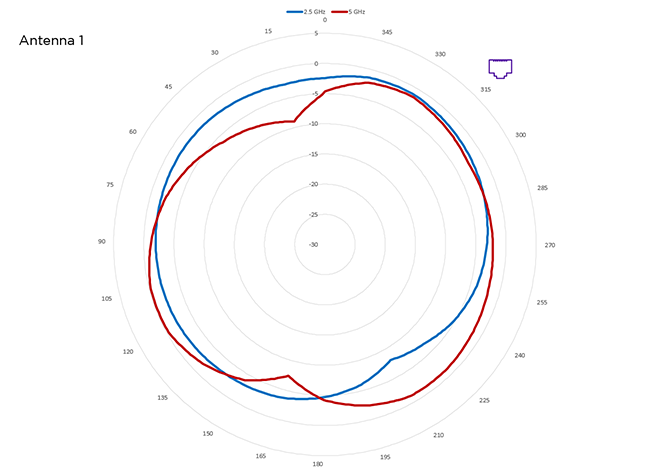
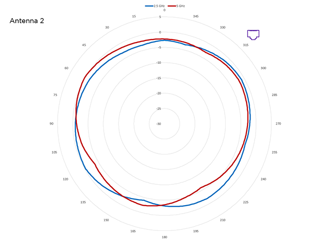
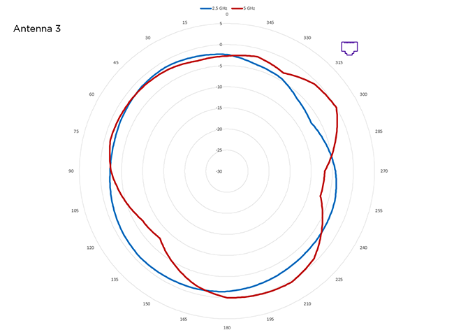
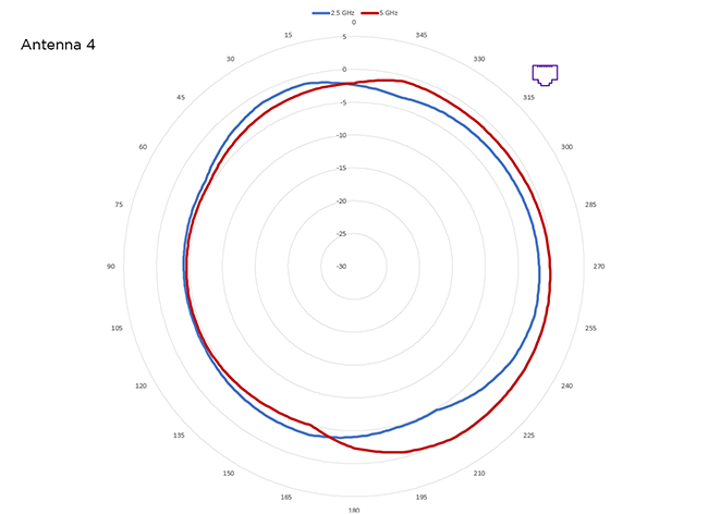
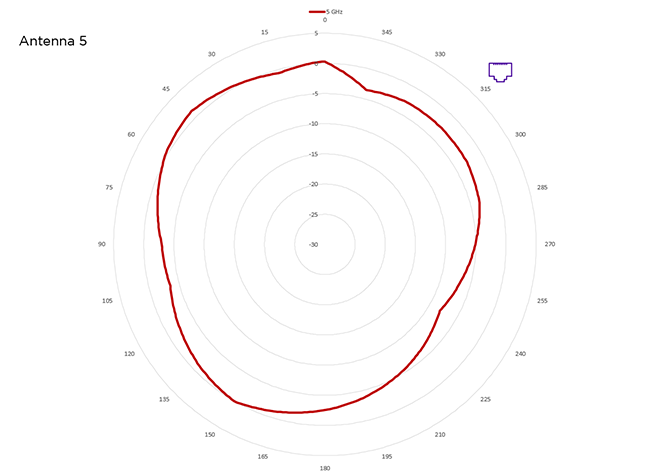
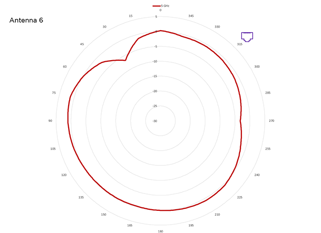
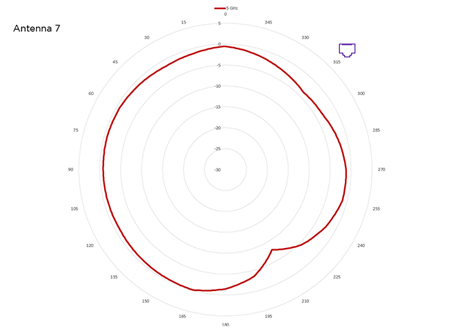
Antenna Plots
The antenna plots for these devices are shown below. The Ethernet port location is noted on each chart.
Antenna 1
Antenna 2
Antenna 3
Antenna 4
Antenna 5
Antenna 6
Antenna 7
Power Specifications
Power Options
Power draw w/o USB: typical 19.2 W, maximum 20.8 W
802.3at PoE capable Gigabit Ethernet port (RJ45 power input pins: wires 4, 5, 7, 8 or 1, 2, 3, 6)
PoE input:
Typical:
54V ⎓ DC, 0.40A 21.7W Max. PoE with USB 2.5W (IEEE 802.3at only 42.5-57VDC, USB 0.5A)
54V ⎓ DC, 0.45A 19.2W Max. PoE without USB (IEEE 802.3af 37-42.5VDC)
Maximum:
Power Profile
| AP460C | 802.3af | 802.3at |
|---|---|---|
| 2.4 G Radio | 2x2 (14 dBm) | 2x2 (18 dbm) |
| 5 G Radio | 2x2 (17 dBm) | 4x4 (18 dBm) |
| Sensor Radio | 2.4 G and 5 G (15 dBm) | 2.4 G and 5 G (18 dBm) |
| BLE | Enabled | Enabled |
| USB | No | Yes |
| 2.5 G Ethernet | Yes | Yes |
| 1 G Ethernet | No | Yes |
Environmental Specifications
The regulatory compliance statements in this section apply to Extreme NetworksAP460C, AP460S6C, and AP460S12C devices.
Japan Indoor Use
Note
For Japan, 5150-5350 MHz band is restricted for indoor use only for AP460C, AP460S6C, and AP460S12C. 
Compliance Statement - Europe
EU Declaration of Conformity
View full CE Declaration of Compliance and this information online at www.aerohive.com/support/regulatory-compliance
Extreme Networks, Inc. declares that this device complies with the essential requirements of the Radio Eqiupment Directive 2014/53/EU.
Radio Specifications
Bluetooth BLE Beacon
USA, Canada, and Taiwan Radio Frequency Bands
a. USA
b. Canada
Indoor: 802.11a/n/ac/ax: 5 GHz band: 5150-5350, 5470-5600, 5650-5850 MHz
c. Taiwan
l 802.11b/g/n/ac: 2.4 GHz band: 2412-2462 MHz
l 802.11a/n/ac/ax: 5 GHz band: 5180-5320, 5500-5825 MHz
l BLE: 2412-2462 MHz
EU Radio Frequency and Power Levels
This product supports the following radio frequencies and power levels in the EU version:
Bulgarian [български]: Този продукт поддържа следните радиочестоти и нива на мощност във версията на ЕС:
Croatian [hrvatski]: Ovaj proizvod podržava sljedeće radijske frekvencije i razinu snage u verziji EU:
Česky [Czech]: [Tento produkt podporuje následující rádiové frekvence a úrovně výkonu ve verzi EU:
Danish [Dansk]: Dette produkt understøtter følgende radiofrekvenser og strømniveauer i EU-versionen:
Dutch [Nederland]: Dit product ondersteunt de volgende radiofrequenties en vermogensniveaus in de EU-versie:
English: This product supports the following radio frequencies and power levels in the EU version:
Estonian [Eesti]: See toode toetab järgmisi raadiosagedusi ja võimsuse taseme ELis versioon:
Finnish [Suomi]: Tämä tuote tukee seuraavia radiotaajuuksia ja tehoja EU-versiossa:
French [Français]: Ce produit prend en charge les fréquences radio et les niveaux de puissance suivants dans la version EU:
German [Deutsch]: Dieses Produkt unterstützt die folgenden Funkfrequenzen und Leistungsstufen in der EU-Version:
Greek [Ελληνική] Αυτό το προϊόν υποστηρίζει τις ακόλουθες ραδιοσυχνότητες και επίπεδα ισχύος στην έκδοση της ΕΕ:
Hungarian [Magyar]: Ez a termék a következő rádiófrekvenciákat és teljesítményszinteket támogatja az EU verziójában :
Italian [Italiano]: Questo prodotto supporta le seguenti frequenze radio e livelli di potenza nella versione UE:
Latvian [Latviski]: Šis produkts atbalsta šādus radio frekvences un jaudas līmeni ES versiju:
Lithuanian [Lietuvių]: Šis produktas palaiko šiuos radijo dažnius ir galios lygį ES versija:
Maltese [Malti]: Dan il-prodott jappoġġja l-frekwenzi tar-radju li ġejjin u l-livelli ta 'enerġija fil-verżjoni UE:
Pollish [Polski]: Ten produkt obsługuje następujące częstotliwości radiowe i poziomy mocy w wersji unijnej:
Portuguese [Português]: Este produto suporta as seguintes frequências de rádio e níveis de potência na versão UE:
Romanian [Romania]: This product supports the following radio frequencies and power levels in the EU version
Slovak [Slovensky]:Tento produkt podporuje nasledujúce rádiové frekvencie a úrovne napájania vo verzii EÚ:
Slovenian [Slovenija]: Ta izdelek podpira te radijske frekvence in ravni moči v različici EU:
Spanish [Español]: Este producto admite las siguientes frecuencias de radio y niveles de potencia en la versión de la UE:
Swedish [Sverige]: Denna produkt stöder följande radiofrekvenser och effektnivåer i EU-versionen:
UK: This product supports the following radio frequencies and power levels in the EU version:
EU Radiation Warning Statement

To meet radiation exposure requirements, these devices should be installed at a minimum distance of 7.87" (20 cm) from people or animals.
Restrictions: 5150-5350 MHz for indoor use only.
Bulgarian [български]: За да отговарят на изискванията за излагане на радиация, тези устройства трябва да бъдат инсталирани на минимално разстояние от 20 см от хората или животните.
Ограничения: 5150-5350 MHz само за вътрешна употреба.
Croatian [hrvatski]: Da bi zadovoljili zahtjeve izloženosti zračenju, ti uređaji trebaju biti instalirani na minimalnoj udaljenosti od 20 cm od ljudi ili životinja.
Ograničenja: 5150-5350 MHz samo za unutarnju uporabu.
Czech [Česky]: Aby byly splněny požadavky na ozáření, měly by být tato zařízení instalována v minimální vzdálenosti 20 cm od lidí nebo zvířat.
Omezení: 5150-5350 MHz pouze pro vnitřní použití.
Danish [Dansk]: For at opfylde kravene til strålingseksponering skal disse enheder installeres i mindst 7.87" (20 cm) afstand fra mennesker eller dyr.
Restriktioner: 5150-5350 MHz kun til indendørs brug.
Dutch [Nederland]: Om aan stralingsblootstelling te voldoen, dienen deze apparaten op een minimumafstand van 7.87" (20 cm) van mensen of dieren te worden geïnstalleerd.
Beperkingen: 5150-5350 MHz alleen voor gebruik binnenshuis.
English: To meet radiation exposure requirements, these devices should be installed at a minimum distance of 7.87" (20 cm) from people or animals.
Restrictions: 5150-5350 MHz for indoor use only.
Estonian [Eesti]: Et rahuldada kiirituse nõuetele, need seadmed tuleb paigaldada minimaalselt 7.87" (20 cm) inimestelt või loomadelt.
Piirangud: 5150-5350 MHz sisetingimustele.
Finnish [Suomi]: Säteilytysvaatimusten täyttämiseksi nämä laitteet on asennettava vähintään 7.87" (20 cm) etäisyydelle ihmisistä tai eläimistä.
Rajoitukset: 5150-5350 MHz vain sisäkäyttöön.
French [Français]: Pour répondre aux exigences d'exposition aux rayonnements, ces appareils devraient être installés à une distance minimale de 7.87" (20 cm) des personnes ou des animaux.
Restrictions: 5150-5350 MHz pour usage intérieur seulement.
German [Deutsch]: Um die Anforderungen an die Strahlenbelastung zu erfüllen, sollten diese Geräte in einem Abstand von 7.87" (20 cm) von Personen oder Tieren installiert werden.
Einschränkungen: 5150-5350 MHz nur für den Innenbereich.
Greek [Ελληνική]: Για την κάλυψη των απαιτήσεων έκθεσης σε ακτινοβολία, οι συσκευές αυτές πρέπει να τοποθετούνται σε απόσταση τουλάχιστον 20 cm από ανθρώπους ή ζώα.
Περιορισμοί: 5150-5350 MHz μόνο για εσωτερική χρήση.
Hungarian [Magyar]: A sugárterhelési követelmények teljesítése érdekében ezeket az eszközöket legalább 7.87" (20 cm) távolságra kell felszerelni az emberek vagy az állatoktól.
Korlátozások: 5150-5350 MHz csak beltéri használatra.
Italian [Italiano]: Per soddisfare i requisiti di esposizione alle radiazioni, questi dispositivi devono essere installati ad una distanza minima di 20 cm da persone o animali.
Restrizioni: 5150-5350 MHz solo per uso interno.
Latvian [Latviski]: Lai apmierinātu starojuma iedarbības prasībām, šīs ierīces ir uzstādītas pie minimālo attālumu 7.87" (20 cm) no cilvēkiem vai dzīvniekiem.
Ierobežojumi: 5150-53250 MHz izmantot tikai telpās.
Lithuanian [Lietuvių]: Siekiant patenkinti SPINDULIAVIMĄ reikalavimus, šie įtaisai turi būti įrengiami ne arčiau kaip 7.87" (20 cm) nuo žmonių ar gyvūnų.
Apribojimai: 5150-5350 MHz naudoti tik patalpose.
Maltese [Malti]: Biex jilħqu l-ħtiġiet ta 'espożizzjoni tar-radjazzjoni, dawn il-mezzi għandhom jiġu installati f'distanza minima ta' 7.87" (20 ċm) minn nies jew annimali.
Restrizzjonijiet: MHz 5150-5350 għall-użu fuq ġewwa biss.
Polish [Polski]: Aby spełnić wymagania dotyczące narażenia na promieniowanie, urządzenia te powinny być instalowane w odległości minimum 7.87" (20 cm) od ludzi lub zwierząt.
Ograniczenia: 5150-5350 MHz tylko do użytku wewnętrznego.
Portuguese [Português]: Para atender aos requisitos de exposição à radiação, esses dispositivos devem ser instalados a uma distância mínima de 20 cm (7.87") de pessoas ou animais.
Restrições: 5150-5350 MHz para uso interno apenas.
Romanian [Romania]: Pentru a îndeplini cerințele de expunere la radiații, aceste dispozitive ar trebui instalate la o distanță minimă de 20 cm de la oameni sau animale.
Restricții: 5150-5350 MHz numai pentru uz intern.
Slovak [Slovensky]: Ak chcete splniť požiadavky na vystavenie žiareniu, mali by byť tieto zariadenia inštalované v minimálnej vzdialenosti od ľudí alebo zvierat od minimálnej vzdialenosti 20 cm.
Obmedzenia: 5150-5350 MHz iba pre vnútorné použitie.
Slovenian [Slovenija]: Da bi zadovoljili zahteve izpostavljenosti sevanja, morajo biti te naprave nameščene na razdalji najmanj 7.87" (20 cm) iz ljudi ali živali.
Omejitve: 5150-5350 MHz samo za uporabo v zaprtih prostorih.
Spanish [Español]: Para cumplir con los requisitos de exposición a la radiación, estos dispositivos deben instalarse a una distancia mínima de 7.87" (20 cm) de personas o animales.
Restricciones: 5150-5350 MHz sólo para uso en interiores.
Swedish [Sverige]: För att uppfylla kraven på strålningsexponering bör dessa enheter installeras på minst 7.87" (20 cm) från människor eller djur.
Restriktioner: 5150-5350 MHz endast för inomhusbruk.
Federal Communication Commission Interference Statement
This equipment has been tested and found to comply with the limits for a Class B digital device, pursuant to Part 15 of the FCC Rules. These limits are designed to provide reasonable protection against harmful interference in a residential installation. This equipment generates, uses and can radiate radio frequency energy and, if not installed and used in accordance with the instructions, may cause harmful interference to radio communications. However, there is no guarantee that interference will not occur in a particular installation. If this equipment does cause harmful interference to radio or television reception, which can be determined by turning the equipment off and on, the user is encouraged to try to correct the interference by one of the following measures:
FCC Caution: Any changes or modifications not expressly approved by the party responsible for compliance could void the user's authority to operate this equipment.
This device complies with Part 15 of the FCC Rules. Operation is subject to the following two conditions: (1) This device may not cause harmful interference, and (2) this device must accept any interference received, including interference that may cause undesired operation.
IMPORTANT NOTE:
Radiation Exposure Statement:
This equipment complies with FCC radiation exposure limits set forth for an uncontrolled environment. This equipment should be installed and operated with minimum distance of 9.84" (25 cm) between the radiator and people or animals.
This transmitter must not be co-located or operating in conjunction with any other antenna or transmitter.
Country Code selection feature to be disabled for products marketed to the US/CANADA.
Warning: This is a Class A product. In a domestic environment this product may cause radio interference in which case the user may be required to take adequate measures.
Este equipamento não tem direito à proteção contra inteferência prejudicial e não pode causar interferência em sistemas devidamente autorizados.
La operación de este equipo está sujeta a las siguientes dos condiciones
(1) es posible que este equipo o dispositivo no cause interferencia perjudicial y
(2) este equipo o dispositivo debe aceptar cualquier interferencia, incluyendo la que pueda causar su operación no deseada.
The operation of this equipment is subject to the following two conditions:
(1) it is possible that this equipment or device does not cause disruptive interference and
(2) this equipment or device must accept any interference, including interference that may cause undesired operation).
Industry Canada Statement:
This device complies with Industry Canada license-exempt RSS standards. Operation is subject to the following two conditions:
Le présent appareil est conforme aux CNR d'Industrie Canada applicables aux appareils radio exempts de licence. L'exploitation est autorisée aux deux conditions suivantes :
Caution:
(i) the device for operation in the band 5150-5250 MHz is only for indoor use to reduce the potential for harmful interference to co-channel mobile satellite systems;
Avertissement:
(i) les dispositifs fonctionnant dans la bande 5150-5250 MHz sont réservés uniquement pour une utilisation à l’intérieur afin de réduire les risques de brouillage préjudiciable aux systèmes de satellites mobiles utilisant les mêmes canaux;
Dynamic Frequency Selection (DFS):
Dynamic Frequency Selection (DFS) for devices operating in the bands 5250- 5350 MHz, 5470-5600 MHz and 5650-5725 MHz.
Sélection dynamique de fréquences (DFS):
Sélection dynamique de fréquences (DFS) pour les dispositifs fonctionnant dans les bandes 5250-5350 MHz, 5470-5600 MHz et 5650-5725 MHz.
Radiation Exposure Statement:
This equipment complies with IC radiation exposure limits set forth for an uncontrolled environment. This equipment should be installed and operated with minimum distance 30 cm between the radiator and people or animals.
Déclaration d'exposition aux radiations:
Cet équipement est conforme aux limites d'exposition aux rayonnements IC établies pour un environnement non contrôlé. Cet équipement doit être installé et utilisé avec un minimum de 30 cm de distance entre la source de rayonnement et des personnes ou des animaux.
Taiwan Compliance Information
Extreme Networks AP460C, AP460S6C, and AP460S12C
取得審驗證明之低功率射頻器材,非經核准,公司、商號或使用者均不得擅自變更頻率、加大功率或變更原設計之特性及功能。
低功率射頻器材之使用不得影響飛航安全及干擾合法通信;經發現有干擾現象時,應立即停用,並改善至無干擾時方得繼續使用。前述合法通信,指依電信管理法規定作業之無線電通信。低功率射頻器材須忍受合法通信或工業、科學及醫療用電波輻射性電機設備之干擾。
應避免影響附近雷達系統之操作
Taiwan MPE Warning
電磁波曝露量MPE標準值(MPE) 1mW/cm2,送測產品實值為0.6262 mW/cm2
"avoid affecting the operation of nearby radar systems". 應避免影響附近雷達系統之操作
" High-gain directional antennas can only be used in stationary point-to-point systems." 高增益指向性天線只得應用於固定式點對點系統。
Copyright © 2020 Extreme Networks. All rights reserved. Published March 2020.