Home > Hardware > ap > AP170 Hardware User Guide

|
AP170 Hardware User Guide
Read about and view specifications for the AP170 in this topic. Install the AP170 using this topic.
If your access point is configured for the World Regulatory Domain, it is important to set the country code to the country in which the AP will be deployed to meet regulatory requirements and for optimal wireless operation. To do this, follow these steps:

Note
The country code selection is for World models only and is not available to FCC, CAN, and other country-specific models. Per FCC regulations, all Wi-Fi products marketed in the United States must be set to U.S. channels only.For Devices Running HiveManager
For Devices Running HiveManager Classic
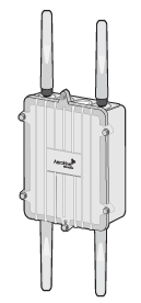
The AP170 is a multi-channel mesh wireless access point with a watertight chassis that can be deployed in virtually any outdoor setting, including extreme environments.
With four antennas and the ability to provide service concurrently on both 2.4 GHz and 5 GHz bands, the AP170 supports 802.11n and legacy 802.11a, b, and g clients. The device provides 2x2:2 MIMO and a single 10/100/1000 Ethernet port through which it is powered using PoE (power over Ethernet) that follows the IEEE 802.3at standard.
The Extreme AP170 is specifically designed for outdoor high-bandwidth wireless deployments in harsh environments. The AP170 supports a variety of authentication and security protocols, including Wi-Fi CERTIFIED™ WPA™ and WPA2™, 802.11i, WEP, 802.1X, PSK, Extreme Networks’s patented PPSK, and AES:CCMP, TKIP, and RC4 (WEP only) encryption.
For more information about Extreme Networks APs in general, see Introduction to Extreme APs
For information about connecting your AP to the network, best-practices, and troubleshooting, see Onboarding New Devices Troubleshooting Tips
For compliance information for these devices, see http://www.aerohive.com/support/tech-docs-and-online-training.
Safety Guidelines
The information in this section applies to the AP170 devices.
The following safety icons are used in these guidelines to identify the type of precaution:

|
This icon indicates a general caution. Failure to comply with a caution notification can result in damage to equipment. |

|
This icon indicates an electrical caution. Failure to comply with an electrical notification can result in serious injury or death, and extensive damage to equipment. |

|
This icon indicates a laser caution. Failure to comply with a laser caution can result in serious injury. |
| The following table lists the safety precautions you should follow when installing your AP170 device. | |
|
|
Extreme Networks devices must be installed by a professional installer who is certified to install these types of devices and to ensure that they are properly grounded and meets applicable local and national electrical codes. |
|
|
Do not install the device in an environment where the operating ambient temperature might exceed the recommended ranges. |
|
|
If you install the AP170 in wet, windy location, make sure to install the Ethernet cable housing for a complete waterproof connection. |
|
|
To protect the AP170 from lightning, do not place it at the highest point of a building or structure. |
|
|
Use only attachments and accessories specified by Extreme Networks. |
|
|
During operation, the surfaces of the AP170 can become hot. Use caution when handling. |
|
|
Electrical equipment generates heat. Ambient air temperature may not be adequate to cool equipment to acceptable operating temperatures without adequate circulation. Be sure that the room where you install your device has adequate air circulation. |
|
|
Changes or modifications made to this device that are not expressly approved by the party responsible for compliance could void the user's authority to operate the equipment. |
|
|
Do not connect or disconnect antennas or cables from the AP170 during periods of lightning activity. |
|
|
Make sure that the AP170 is connected to a suitably installed ground conductor. Contact the appropriate electrical inspection authority if you are uncertain that suitable grounding is available. |
|
|
Do not locate the AP170 enclosure near overhead power lines or other electric light or power circuits, or where it can come into contact with such circuits. During installation, exercise extreme care not to come into contact with these circuits, which can cause serious injury or death. For proper installation and grounding of the product, refer to national and local electrical codes: NFPA (National Fire Protection Association) 70, National Electrical Code Article 810 (U.S.); Canadian Electrical Code, Part I, CSA 22.1 and Section 54 (Canada); and if local or national electrical codes are not available, refer to IEC (International Electrotechnical Commission) 364, Part 1 through 7 (other countries). |
|
|
Electrostatic discharge (ESD) can damage equipment and impair electrical circuitry. ESD damage occurs when electronic components are improperly handled and can result in complete or intermittent failures. Be sure to follow ESD-prevention procedures when handling electronic components. |
|
|
Disconnect all power by turning off the power switch and unplugging the power cord before installing or removing a device, or working near power supplies. |
|
|
Never assume that power is disconnected from a circuit; always check the circuit. |
|
|
Explosion risk - There is a risk of an explosion if the lithium battery (for the CMOS clock) is replaced with an incompatible battery type. Battery replacement should be performed only by a trained electrician or technician who is able to understand all installation and device specifications. |
|
|
Lithium battery disposal - Regulations and laws pertaining to the recycling and disposal of lithium ion batteries vary from country to country as well as by state and local governments. European governments have more strict regulations on the disposal of rechargeable batteries than the USA and Canada. Check the laws and regulations where you live before disposing of lithium batteries. |
|
|
To comply with RF (radio frequency) exposure limits, do not place the AP170 within 9.05" (23 cm) of people or animals when using omnidirectional antennas. If you are using a point-to-point mesh directional antenna, do not place the AP170 within 26" (65 cm) of people. |
Install the AP170
This section explains how to mount an AP170 to a pole or flat surface in virtually any outdoor setting, and connect it to ExtremeCloud IQ over the network.
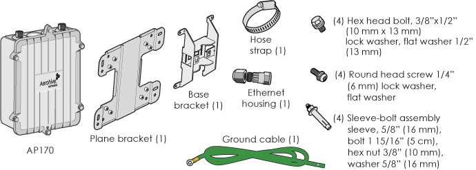
To install your AP170, you will need the following accessories (ordered separately) and tools:
Shipping Carton Contents
The AP170 shipping carton includes the items shown in this illustration.
When you mount the AP170 you can adjust the orientation to vertical for optimum radio transmission. For example, you can mount the AP170 on a non-penetrating roof stand or to a Winegard bracket, often used for mounting satellite dishes. The mounting bracket accommodates poles with a 1" to 3.5" (2.5 cm to 8.9 cm) diameter.
For unobstructed RF coverage, mount the AP170 in a relatively open area. At a minimum, mount it on a pole, mast, or flat surface. These options are described below. The following illustration shows an AP170 mounted on a vertical pole with the major devices and accessories called out.
Note
For best performance, install APs at least 100' (30.5 m) apart. 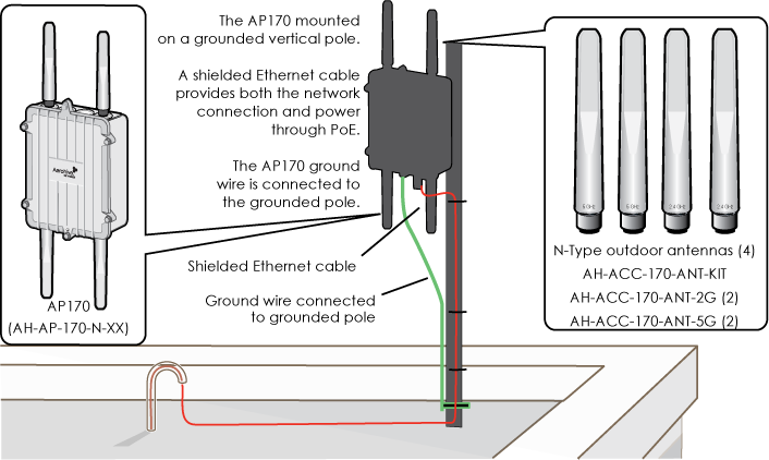
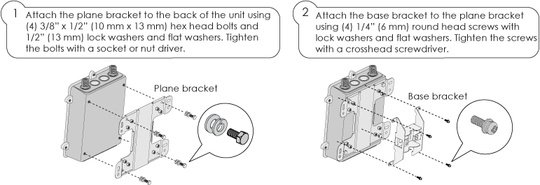
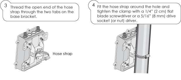
Vertical Pole Mount
The steps in the following illustrations explain how to mount the AP170 on a vertical pole.
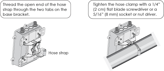
Horizontal Pole Mount
The following steps and illustrations explain how to mount the AP170 on a horizontal pole.
Note
When attaching the AP170 to a horizontal pole, such as the arm of a street light, make sure that the face of the device is perpendicular to the Earth for optimal RF coverage, as shown here: 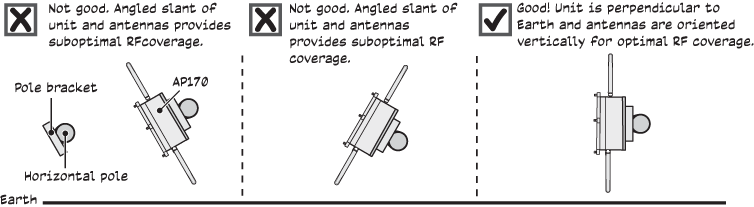
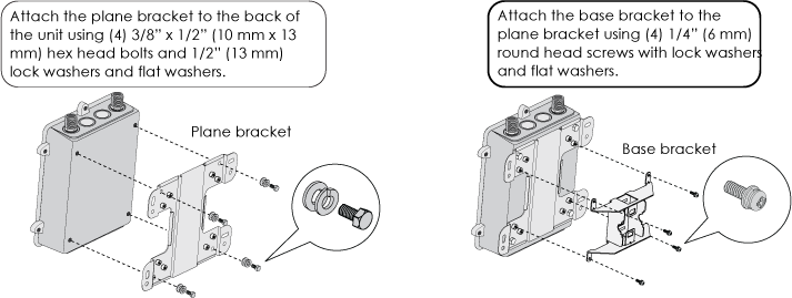
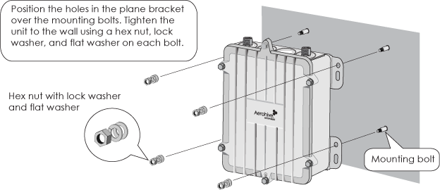
Flat Surface Mount
The following steps explain how to mount the AP170 on a flat surface. You will need the plane bracket and the four sleeve-bolt assemblies.
Note
If you are installing the device on a concrete wall, you can use 2" (5 cm) threaded screws and plastic wall anchors (not supplied) to mount the device. 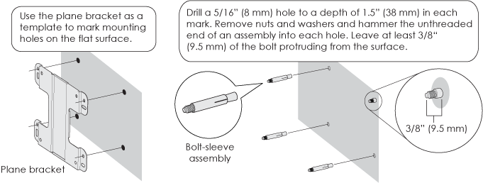
Make sure you ground the AP as described in "Grounding the AP170".
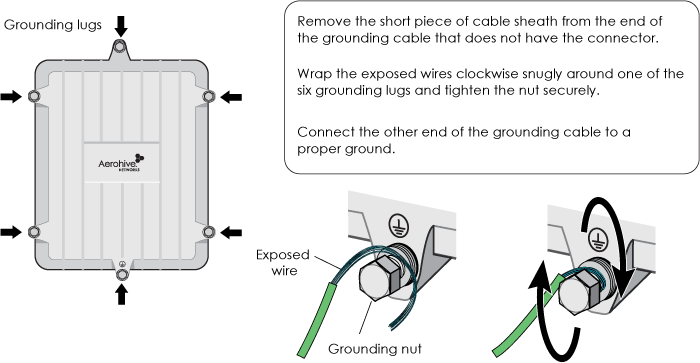
Grounding the AP170
When you have completed the mounting steps, you must ground the device. Connect one end of the grounding cable to the grounding lug on the chassis and the other end to an appropriate ground.
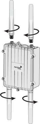
Attaching External Antennas
Once you have grounded the AP170, you are ready to connect the antennas.
Note
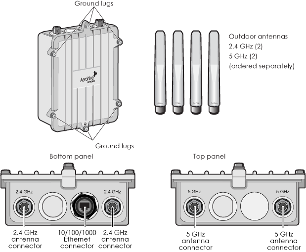
It is extremely important to properly ground your device to complete your installation.The omnidirectional antennas are available from Extreme Networks (SKUs AH-ACC-170-ANT-2G, AH-ACC-170-ANT-5G). These antennas fit the N-type antenna connectors on the top and bottom of the AP170. The two connectors on the bottom of the unit are for the 2.4 GHz antennas, and the two on the top of the unit are for the 5 GHz antennas (device and antennas are labeled).
To connect the antennas, screw them onto the antenna connectors by hand, turning them clockwise until tight.
Note
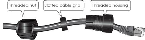
You do not need to use a tool to tighten the antennas or apply self-amalgamating PTFE (polytetrafluoroethylene) tape about the threads of the connectors to create a waterproof seal.Attaching the Ethernet Cable Waterproof Housing
The following steps explain how to ensure a weatherproof seal for the Ethernet cable using the waterproof housing assembly shown in the figure.
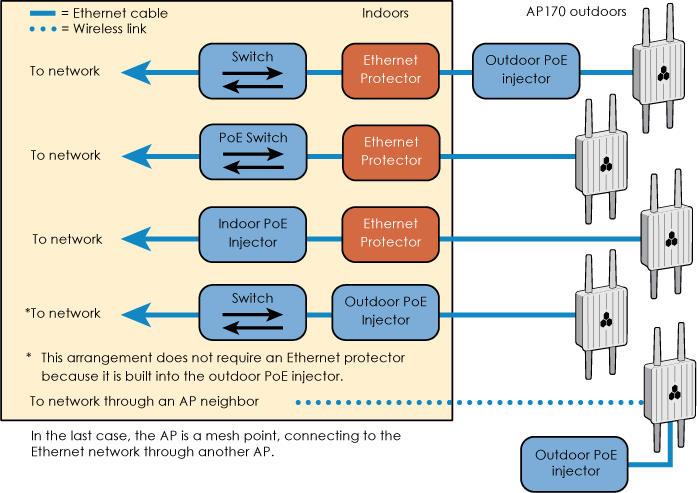
PoE and Ethernet Protection
In most cases, you can connect an Ethernet cable directly from the AP170 to a PoE-enabled switch or to a PoE injector (AH-ACC-INJ-30W-XX) inside the building. In some cases, you might need to install an outdoor waterproof PoE injector, available separately (AH-ACC-OINJ-30W).
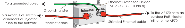
The AP170 and outdoor PoE injectors have built-in surge protection to guard against lightning strikes. However, the network where the Ethernet cable enters the building requires protection as well. To prevent the indoor network from power surges caused by lightning, place an Ethernet protector (AH-ACC-1G-ETH-PROT) inline between the AP and the rest of the network as shown here.
Hardware Components
You can see the hardware components for both models in the following illustration, and read about them in the descriptions that follow.
AP170 Chassis
The durable, weatherproof AP170 chassis is designed for deployment in extreme conditions. Features include six grounding lugs, four antenna connectors, and a waterproof 10/100/1000 Ethernet connector. The device ships with a complete mounting kit.
Ethernet Port
The PoE 10/100/1000Base-T/TX Ethernet port accepts standard Cat5, Cat5e, or Cat6 Ethernet cable and is powered from 802.3at-compatible PSE (power sourcing equipment). PSE can be embedded in a switch or router, or can be a separate device that injects power into the Ethernet line en route to the AP.
With 802.3at, the 1/2 and 3/6 wire pairs connect to DC source 1, and 4/5 and 7/8 pairs to DC source 2 in PSE. Although the exact polarity depends on the PSE design, the AP170 Ethernet port can support all options.
Antennas
The AP170 supports four external antennas; two 2.4 GHz band (IEEE 802.11b/g/n) with a 5 dBi gain, and two 5 GHz band (IEEE 802.11a/n) with a 7 dBi gain. The antennas are omnidirectional, providing fairly equal coverage in all directions in a toroidal (donut-shaped) pattern around each antenna. For greater coverage on a horizontal plane, it is best to orient the device so that the antennas are vertical.
The two 2.4 GHz antennas link to a 2.4 GHz radio for 802.11b/g/n, and the two 5 GHz antennas link to the a 5 GHz radio for 802.11a/n. The two radios can operate concurrently.
The AP170 has four antenna connectors. Two connectors on the top panel support 5 GHz antennas, and two connectors on the bottom panel support 2.4 GHz antennas. You must install an antenna in every connector.
Although hive members automatically adjust their signal strength according to their environments, you can manually resize the area of coverage by increasing or decreasing the signal strength. To resize the coverage area, enter the interface { wifi0 | wifi1 } radio power <number> command, where <number> can be from 1 to 20 and represents a value in dBm.
Power Connector
Power the device through the ETH0 port from PSE (power sourcing equipment) that is compatible with the 802.3af and 802.3at standards. Because there is no on/off switch, these devices automatically power on when you connect them to power.
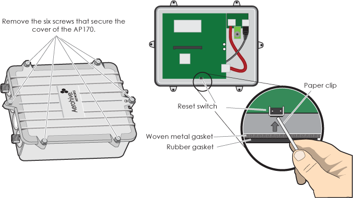
Accessing the Internal Reset Switch
Although not recommended, you can remove the cover the AP170 to access the internal reset switch if necessary. The following steps describe this process.
Note
Be very careful not to disturb the black rubber and woven metal gaskets when removing or replacing the device top. These gaskets are essential for weatherproofing the device.
The following specifications describe the hardware components, PoE electrical requirements, and the environmental ranges in which the device can operate.
Device Specifications
Power Specifications
Environmental Specifications
Ethernet Protector Specifications
Copyright © 2020 Extreme Networks. All rights reserved. Published March 2020.