When calibration is initiated, Smart RF instructs adopted radios (within a selected RF Domain) to beacon on a specific legal channel, using a specific transmit power setting. Smart RF measures the signal strength of each beacon received from both managed and unmanaged neighboring APs to define a RF map of the neighboring radio coverage area. Smart RF uses this information to calculate each managed radio's RF configuration as well as assign radio roles, channel and power.
Within a well planned RF Domain, any associated radio should be reachable by at least one other radio. The Smart RF feature records signals received from its neighbors. access point to access point distance is recorded in terms of signal attenuation. The information is used during channel assignment to minimize interference.
To conduct Smart RF calibration for a controller, service platform or access point RF Domain:
Select Operations.
Select Smart RF.
Expand the System mode in the upper, left-hand, side of the user interface to display the RF Domains available for Smart RF calibration.
Select a RF Domain from amongst those displayed.
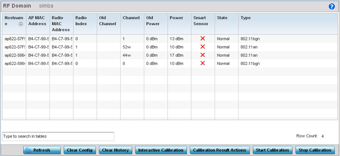
The Smart RF screen displays information specific to the devices within the selected RF Domain using data from the last interactive calibration.
Refer to the following to determine whether a Smart RF calibration or an interactive calibration is required:
|
Hostname |
Displays the administrator assigned Hostname for each member of the RF Domain. |
|
AP MAC Address |
Displays the hardware encoded MAC address assigned to each access point radio within the selected RF Domain. This value cannot be modified as past of a calibration activity. |
|
Radio MAC Address |
Displays the hardware encoded MAC address assigned to each access point radio within the selected RF Domain. This value cannot be modified as part of a calibration activity. |
|
Radio Index |
Displays a numerical index assigned to each listed access point radio when it was added to the network. This index helps distinguish this radio from others within this RF Domain with similar configurations. This value is not subject to change as a result of a calibration activity, but each listed radio index can be used in Smart RF calibration. |
|
Old Channel |
Lists the channel originally assigned to each listed access point MAC address within this RF Domain. This value may have been changed as part an Interactive Calibration process applied to this RF Domain. Compare this Old Channel against the Channel value to right of it (in the table) to determine whether a new channel assignment was warranted to compensate for a coverage hole. |
|
Channel |
Lists the current channel assignment for each listed access point, as potentially updated by an Interactive Calibration. Use this data to determine whether a channel assignment was modified as part of an Interactive Calibration. If a revision was made to the channel assignment, a coverage hole was detected on the channel as a result of a potentially failed or under performing access point radio within this RF Domain. |
|
Old Power |
Lists the transmit power assigned to each listed access point MAC address within this RF Domain. The power level may have been increased or decreased as part an Interactive Calibration process applied to this RF Domain. Compare this Old Power level against the Power value to right of it (in the table) to determine whether a new power level was warranted to compensate for a coverage hole. |
|
Power |
This column displays the transmit power level for the listed access point MAC address after an Interactive Calibration resulted in a power adjustment. This is the new power level defined by Smart RF to compensate for a coverage hole. |
|
Smart Sensor |
Defines whether a listed access point is smart sensor on behalf of the other access point radios comprising the RF Domain. |
|
State |
Displays the current state of the Smart RF managed access point radio. Possible states include: Normal, Offline and Sensor. |
|
Type |
Displays the radio type (802.11an, 802.11bgn etc.) of each listed access point radio within the selected RF Domain. |
Select the Refresh button to (as needed) to update the contents of the Smart RF screen and the attributes of the devices within the selected RF Domain.

Note
Smart RF is not able to detect a voice call in progress, and will switch to a different channel resulting in voice call reconnections.Select the Interactive Calibration button to initiate a Smart RF calibration using the access points within the selected RF Domain. The results of the calibration display within the Smart RF screen. Of particular interest are the channel and power adjustments made by the controller's Smart RF module. Expand the screen to display the Event Monitor to track the progress of the Interactive Calibration.
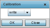
Select the Calibration Result Actions button to launch a sub screen used to determine the actions taken based on the results of the Interactive Calibration. The results of an Interactive calibration are not applied to radios directly, the administrator has the choice to select one of following options:
|
Replace |
Overwrites the current channel and power values with new channel power values the Interactive Calibration has calculated. |
|
Write |
Writes the new channel and power values to the radios under their respective device configurations. |
|
Discard |
Discards the results of the Interactive Calibration without applying them to their respective devices. |
Select the Run Calibration option to initiate a calibration. New channel and power values are applied to radios, they are not written to the running-configuration.
These values are dynamic and may keep changing during the course of the run-time monitoring and calibration the Smart RF module keeps performing to continually maintain good coverage. Unlike an Interactive Calibration, the Smart RF screen is not populated with the changes needed on access point radios to remedy a detected coverage hole. Expand the screen to display the Event Monitor to track the progress of the calibration.
The calibration process can be stopped by selecting the Stop Calibration button.
 Print
this page
Print
this page Email this topic
 Feedback
 View PDF
 Download EPUB