Home > Hardware > ap > AP121 and AP141 Hardware User Guide

|
AP121 and AP141 Hardware User Guide
Read about and view specifications for the AP121 and AP141 in this topic. Install the AP121 or AP141 using this topic.
If your access point is configured for the World Regulatory Domain, it is important to set the country code to the country in which the AP will be deployed to meet regulatory requirements and for optimal wireless operation. To do this, follow these steps:

Note
The country code selection is for World models only and is not available to FCC, CAN, and other country-specific models. Per FCC regulations, all Wi-Fi products marketed in the United States must be set to U.S. channels only.For Devices Running HiveManager
For Devices Running HiveManager Classic
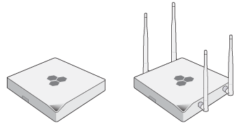
The AP121 and AP141 wireless access points provide dual concurrent 802.11b/g/n and 802.11a/n radios for 2x2:2 MIMO (Multiple Input - Multiple Output) antenna configurations.
When you enable 802.11n high-throughput options such as wide-channel mode (40-MHz channels), A-MPDU and A-MSDU packet aggregation, short guard interval, and MCS15 data rates, they can provide a PHY data rate up to 300 Mbps per radio. The AP121 has four internal antennas, and the AP141 has four detachable external antennas (two 2.4 GHz and two 5 GHz in both cases). Both models have an RJ45 10/100/1000 Ethernet port, an RJ45 console port, and a USB modem port (reserved for future use).
For more information about Extreme Networks APs in general, see Introduction to Extreme APs
For information about connecting your AP to the network, best-practices, and troubleshooting, see Onboarding New Devices Troubleshooting Tips
For regulatory and compliance information, see "Regulatory Compliance Statements".
Safety Guidelines
The cautions and warnings in this section apply to the AP121 and AP141 devices.
The following safety icons are used in these guidelines to identify the type of precaution:

|
This icon indicates a general caution. Failure to comply with a caution notification can result in damage to equipment. |

|
This icon indicates an electrical caution. Failure to comply with an electrical notification can result in serious injury or death, and extensive damage to equipment. |

|
This icon indicates a laser caution. Failure to comply with a laser caution can result in serious injury. |
| The following table lists the safety precautions you should follow when installing your AP121 or AP141 devices. | |
|
|
Extreme Networks devices must be installed by a professional installer who is certified to install these types of devices and to ensure that they are properly grounded and meet applicable local and national electrical codes. |
|
|
These devices are intended for indoor use only. |
|
|
Do not install the device in an environment where the operating ambient temperature might exceed the recommended ranges. |
|
|
Electrical equipment generates heat. Ambient air temperature may not be adequate to cool equipment to acceptable operating temperatures without adequate circulation. Be sure that the room where you install your device has adequate air circulation. |
|
|
Changes or modifications made to this device that are not expressly approved by the party responsible for compliance could void the user's authority to operate the equipment. |
|
|
Electrostatic discharge (ESD) can damage equipment and impair electrical circuitry. ESD damage occurs when electronic components are improperly handled and can result in complete or intermittent failures. Be sure to follow ESD-prevention procedures when handling electronic components. |
|
|
Disconnect all power by turning off the power switch and unplugging the power cord before installing or removing a device, or working near power supplies. |
|
|
Never assume that power is disconnected from a circuit; always check the circuit. |
|
|
Explosion risk - There is a risk of an explosion if the lithium battery (for the CMOS clock) is replaced with an incompatible battery type. Battery replacement should be performed only by a trained electrician or technician who is able to understand all installation and device specifications. |
|
|
Lithium battery disposal - Regulations and laws pertaining to the recycling and disposal of lithium ion batteries vary from country to country as well as by state and local governments. European governments have more strict regulations on the disposal of rechargeable batteries than the USA and Canada. Check the laws and regulations where you live before disposing of lithium batteries. |
|
|
To meet federal radiation exposure requirements, these devices should be installed at a minimum distance of 9.05" (23 cm) from your body. |
The following sections describe how to install your AP121 or AP141 devices, connect them to the network, and start managing them in ExtremeCloud IQ. These instructions apply to both models.
Shipping Carton Contents
The AP121 and AP141 shipping cartons contain the following items:
1 security screw
1 slotted screw
1 wall mount bracket
1 ceiling mount bracket
Note
Antennas for the AP141 must be purchased separately.Mount the AP121 and AP141
Use the rail mount brackets to mount the AP121 or AP141to the tracks of a dropped ceiling grid. Use the mounting plate to mount the AP to any surface that can support its weight (AP121: 11.6 oz or 0.33 kg; AP141: 13.5 oz or 0.38 kg).
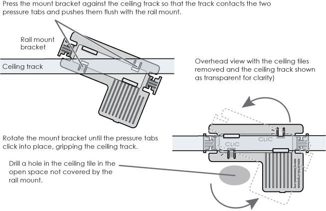
Ceiling Mount
To mount the AP121 or AP141 to a standard 15/16" (2.38 cm) track in a dropped ceiling, use the rail mount bracket that ships with the AP. You will need a drill, and—most likely—a ladder.
Note
Extreme Networks also offers rail mount kits for 9/16" (1.34 cm), and 15/16" (2.38 cm) recessed tracks for AP121, AP141, AP330, and AP350 models (AH-ACC-9-16-CLIP-300-100, and AH-ACC-15-16-CLIP-300-100).
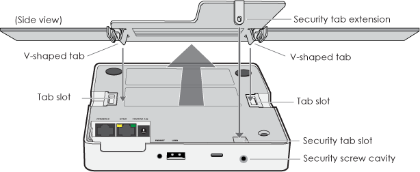
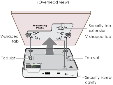
Surface Mount
You can use the flat mounting plate to attach the AP121 or AP141 to any surface that supports its weight (AP121: 11.6 oz or 0.33 kg; AP141: 13.5 oz or 0.38 kg), and to which you can screw or nail the plate. Follow these steps:
Lock the AP121 and AP141
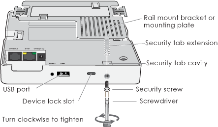
To lock the AP to the rail mount bracket or wall mounting plate, use either a Kensington® lock or the security screw that is included with the mounting kit. To use a Kensington lock, loop the cable attached to the lock around a secure object, insert the T-bar component of the lock into the device lock slot on the AP, and then turn the key to engage the lock mechanism.
To lock the AP to the rail mounting bracket or mounting plate, you can use either the slotted screw or the pan-head security screw, both of which are included in the mounting kit. If you use the security screw, you will need a spanner insert bit for size #6 security screws and a driver handle that will accept the bit. The correct bits are available from Extreme Networksin sets of three for AP121, AP141, AP230, AP330, and AP350models (AH-ACC-SEC-BIT-300-100-3PK). If you use the slotted screw, you can install it with a standard flat-blade screwdriver or pan-head driver bit.
Extreme Networks recommends a variety of Kensington locks. For more information, contact your sales representative.
Hardware Components
You can see the hardware components for both models in the following illustration, and read about them in the descriptions that follow.
Note
To meet federal radiation exposure requirements, these devices should be installed at a minimum distance of 9.05" (23 cm) from your body. 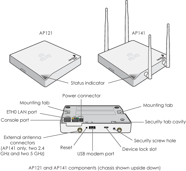
Status Indicator
The status light conveys operational states for system power, firmware updates, Ethernet and wireless interface activity, and major alarms. The AP121 and AP141 have a triangular status light bar on the top left corner of the chassis. The colors of this light indicate the following states of activity:
Dark: There is no power or the status indicator is disabled.
Amber (flashing): This is an alert that indicates that the device is performing a firmware upgrade. Do not power off the device during this process.
Amber (steady): This is an alert that indicates that the CAPWAP connection has not been successfully established, or the device is booting or shutting down.
White: The device is powered on, a successful CAPWAP connection has been made, and the firmware is operating normally.
You can adjust the brightness level to bright or turn it off completely in ExtremeCloud IQ. Navigate to Configure > Network Policy > Additional Settings > Network Service > Management Options. Turn Management Options on and scroll down to the System Settings section. Select the brightness level that you want from the LED brightness drop-down list.
Note
When you change the brightness setting here, the new setting will apply to all devices under this network policy. To change the LED brightness for a single device, establish a console connection and use the CLI command. AP121 and AP141 devices support Bright and Off settings only.To turn the LED on or off or change the brightness using the CLI, enter:
system led brightness [ bright | off ]
For devices running HM Classic, you can set the LEDs for all APs on your network to blink or remain steady. Navigate toHome > Device Management Settings > LED Mode.
Antennas and Antenna Connectors
The AP121 has four internal single-band antennas. The 2.4 GHz antennas (IEEE 802.11b/g/n) have a 2-5 dBi gain. The 5 GHz antennas (IEEE 802.11a/n) have a 3-6 dBi gain. All antennas are omnidirectional and provide fairly equal coverage in all directions.
The AP141 has four male 802.11a/b/g/n RP-SMA (reverse polarity-subminiature version A) external antenna connectors and four external articulated antennas (two 2.4 GHz and two 5 GHz). The external antennas have a 4-dBi gain, are omnidirectional, and provide fairly equal coverage in all directions in a toroidal (donut-shaped) pattern. The antennas and connectors are labeled for easy identification and connection, and swivel in all directions, as shown in this illustration.
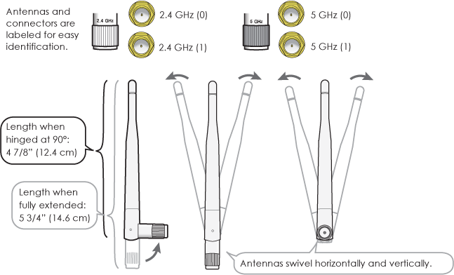
For optimal coverage, align the antennas as shown in the following illustration.
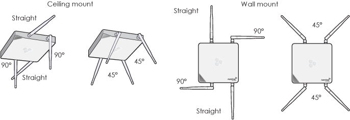
For more information about antennas, see Antennas
Console Port
Through the Console port, you can make a serial connection between your management system and the AP. When you connect to the device using the RJ45 Console port, the management station from which you connect to the device must have a VT100 emulation program, such as Tera Term Pro© (a free terminal emulator) or Hilgraeve HyperTerminal® (provided with Windows® operating systems from XP forward). The serial connection settings are: 9600 bits per second, 8 data bits, no parity, 1 stop bit, and no flow control.
The pin-to-signal mapping for the Console port is shown in Extreme Device Pin Assignments.
Power Connector
There are two ways to power an AP121 or AP141. You can connect a device to a 100 – 240-volt AC power source by connecting an AC/DC power adapter (available as an option) to the 12 V (1.1A) DC connector. You can also power the device through the ETH0 port from PSE (power sourcing equipment) that is compatible with the 802.3af and 802.3at standards. Because there is no on/off switch, these devices automatically power on when you connect them to power.
Ethernet Port LEDs
The ETH0 port has two status LEDs to indicate port operation (yellow for 10/100 Mbps and green for 1000 Mbps). The meanings of the LED colors and patterns are described here:
Dark: No link is detected for this port
Yellow (steady): This port has made a successful 10/100 Mbps link.
Yellow (flashing): This port is sending and receiving traffic at 10/100 Mbps.
Green (steady): This port has made a successful 1000 Mbps link.
Green (flashing): This port is sending and receiving traffic at 1000 Mpbs.
Ethernet Ports
The AP121 and AP141 devices have two RJ45 10/100/1000Base-T/TX Ethernet ports (Eth0 and Eth1) that automatically negotiate half- and full-duplex connections with the connecting device. The ports are autosensing and adjust to straight-through and crossover standard Cat3, Cat5, Cat5e, or Cat6 Ethernet cables automatically. The AP can receive power through an Ethernet connection to the ETH0 port from PSE (power sourcing equipment) that is compatible with the 802.3af standard. Such equipment can be embedded in a switch or router, or it can come from purpose-built devices that inject power into the Ethernet line en route to the AP. Because the PoE port has autosensing capabilities, the wiring termination in the Ethernet cable can be either straight-through or crossover.
Extreme Networks provides the following PoE injectors as an optional accessory:
If an AP is connected to both an AC power source and PSE, the AC power source takes priority. If the device loses power from that source, it automatically switches to PoE. If the AC power comes back online, the AP automatically switches back to AC.
Note
Each time the AP switches from one power source to another, it must reboot.Reset Button
You can use the Reset button to reset the device or restore the factory default settings. Insert a paper clip or similar tool into the pinhole and press the button. To reboot the device, press the button for 5 seconds. To return the configuration to the factory default settings, press it for at least 10 seconds. After releasing the button, the indicator light goes dark, and then glows steady amber while the firmware loads and the system performs a self-test. After the software finishes loading and the AP has connected to ExtremeCloud IQ, the status indicator glows steady white.
To disable the reset button from resetting the configuration, enter this command: no reset-button reset-config-enable. When this feature is disabled, pressing the button for 5 seconds will still reboot the AP, but pressing it for more than 10 seconds will not reset the configuration.
Security Tab Cavity and Screw, and Device Lock Slot
When mounting the AP on a ceiling track or flat surface, you can secure it to the track using the security screw and bracket that ships with the device. You can also physically secure the AP by attaching a lock (such as a Kensington® notebook lock) and cable to the device slot. See "Mount the AP121 and AP141".
USB Modem Port
The USB modem port is reserved for future use.
The following specifications describe the physical features and hardware components, the power adapter and PoE electrical requirements, and the temperature and humidity ranges in which the devices can operate.
Device Specifications
AP121: 6.69" W x 1.63" H x 6.69" D (170 mm W x 41 mm H x 170 mm D)
AP141: 6.69" W x 1.63" H x 7.3 (with antenna connectors) D - (170 mm W x 41 mm H x 185.6 mm D)
AP121: 11.6 oz (0.33 kg)
AP141: 13.5 oz (0.38 kg)
AP121: Two internal omnidirectional 802.11b/g/n antennas, and two internal omnidirectional 802.11a/n antennas
AP141: Two 2.4 GHz and two 5 GHz external omnidirectional 802.11b/g/n articulated antennas
Power Specifications
Input:100 – 240 VAC
Output: 12V/1.1A
Environmental Specifications
The regulatory compliance statements in this section apply to Extreme NetworksAP121 and AP141 devices.
Japan Indoor Use
Note
For Japan, the AP121 and AP141 are restricted for indoor use in the 5150-5350 MHz band only.AP121 and AP141 Compliance Statement - Europe
EU Declaration of Conformity
View this information online at www.aerohive.com/support/regulatory-compliance
Extreme Networks, Inc. declares that this device complies with the essential requirements of the Radio Eqiupment Directive 2014/53/EC.
EU Radio Frequency and Power Levels
This product supports the following radio frequencies and power levels in the EU version:
Bulgarian [български]: Този продукт поддържа следните радиочестоти и нива на мощност във версията на ЕС:
Croatian [hrvatski]: Ovaj proizvod podržava sljedeće radijske frekvencije i razinu snage u verziji EU:
Česky [Czech]: [Tento produkt podporuje následující rádiové frekvence a úrovně výkonu ve verzi EU:
Danish [Dansk]: Dette produkt understøtter følgende radiofrekvenser og strømniveauer i EU-versionen:
Dutch [Nederland]: Dit product ondersteunt de volgende radiofrequenties en vermogensniveaus in de EU-versie:
English: This product supports the following radio frequencies and power levels in the EU version:
Estonian [Eesti]: See toode toetab järgmisi raadiosagedusi ja võimsuse taseme ELis versioon:
Finnish [Suomi]: Tämä tuote tukee seuraavia radiotaajuuksia ja tehoja EU-versiossa:
French [Français]: Ce produit prend en charge les fréquences radio et les niveaux de puissance suivants dans la version EU:
German [Deutsch]: Dieses Produkt unterstützt die folgenden Funkfrequenzen und Leistungsstufen in der EU-Version:
Greek [Ελληνική] Αυτό το προϊόν υποστηρίζει τις ακόλουθες ραδιοσυχνότητες και επίπεδα ισχύος στην έκδοση της ΕΕ:
Hungarian [Magyar]: Ez a termék a következő rádiófrekvenciákat és teljesítményszinteket támogatja az EU verziójában :
Italian [Italiano]: Questo prodotto supporta le seguenti frequenze radio e livelli di potenza nella versione UE:
Latvian [Latviski]: Šis produkts atbalsta šādus radio frekvences un jaudas līmeni ES versiju:
Lithuanian [Lietuvių]: Šis produktas palaiko šiuos radijo dažnius ir galios lygį ES versija:
Maltese [Malti]: Dan il-prodott jappoġġja l-frekwenzi tar-radju li ġejjin u l-livelli ta 'enerġija fil-verżjoni UE:
Pollish [Polski]: Ten produkt obsługuje następujące częstotliwości radiowe i poziomy mocy w wersji unijnej:
Portuguese [Português]: Este produto suporta as seguintes frequências de rádio e níveis de potência na versão UE:
Romanian [Romania]: This product supports the following radio frequencies and power levels in the EU version
Slovak [Slovensky]:Tento produkt podporuje nasledujúce rádiové frekvencie a úrovne napájania vo verzii EÚ:
Slovenian [Slovenija]: Ta izdelek podpira te radijske frekvence in ravni moči v različici EU:
Spanish [Español]: Este producto admite las siguientes frecuencias de radio y niveles de potencia en la versión de la UE:
Swedish [Sverige]: Denna produkt stöder följande radiofrekvenser och effektnivåer i EU-versionen:
EU Radiation Warning Statement
To meet radiation exposure requirements, these devices should be installed at a minimum distance of 9.05" (23 cm) from people or animals.
Restrictions: 5150-5250 MHz for indoor use only.
Bulgarian [български]: За да отговарят на изискванията за излагане на радиация, тези устройства трябва да бъдат инсталирани на минимално разстояние от 23 см от хората или животните.
Ограничения: 5150-5250 MHz само за вътрешна употреба.
Croatian [hrvatski]: Da bi zadovoljili zahtjeve izloženosti zračenju, ti uređaji trebaju biti instalirani na minimalnoj udaljenosti od 23 cm od ljudi ili životinja.
Ograničenja: 5150-5250 MHz samo za unutarnju uporabu.
Czech [Česky]: Aby byly splněny požadavky na ozáření, měly by být tato zařízení instalována v minimální vzdálenosti 23 cm od lidí nebo zvířat.
Omezení: 5150-5250 MHz pouze pro vnitřní použití.
Danish [Dansk]: For at opfylde kravene til strålingseksponering skal disse enheder installeres i mindst 9.05" (23 cm) afstand fra mennesker eller dyr.
Restriktioner: 5150-5250 MHz kun til indendørs brug.
Dutch [Nederland]: Om aan stralingsblootstelling te voldoen, dienen deze apparaten op een minimumafstand van 9.05" (23 cm) van mensen of dieren te worden geïnstalleerd.
Beperkingen: 5150-5250 MHz alleen voor gebruik binnenshuis.
English: To meet radiation exposure requirements, these devices should be installed at a minimum distance of 9.05" (23 cm) from people or animals.
Restrictions: 5150-5250 MHz for indoor use only.
Estonian [Eesti]: Et rahuldada kiirituse nõuetele, need seadmed tuleb paigaldada minimaalselt 9.05 " (23 cm) inimestelt või loomadelt.
Piirangud: 5150-5250 MHz sisetingimustele.
Finnish [Suomi]: Säteilytysvaatimusten täyttämiseksi nämä laitteet on asennettava vähintään 9.05" (23 cm) etäisyydelle ihmisistä tai eläimistä.
Rajoitukset: 5150-5250 MHz vain sisäkäyttöön.
French [Français]: Pour répondre aux exigences d'exposition aux rayonnements, ces appareils devraient être installés à une distance minimale de 9.05" (23 cm) des personnes ou des animaux.
Restrictions: 5150-5250 MHz pour usage intérieur seulement.
German [Deutsch]: Um die Anforderungen an die Strahlenbelastung zu erfüllen, sollten diese Geräte in einem Abstand von 9.05" (23 cm) von Personen oder Tieren installiert werden.
Einschränkungen: 5150-5250 MHz nur für den Innenbereich.
Greek [Ελληνική]: Για την κάλυψη των απαιτήσεων έκθεσης σε ακτινοβολία, οι συσκευές αυτές πρέπει να τοποθετούνται σε απόσταση τουλάχιστον 23 cm από ανθρώπους ή ζώα.
Περιορισμοί: 5150-5250 MHz μόνο για εσωτερική χρήση.
Hungarian [Magyar]: A sugárterhelési követelmények teljesítése érdekében ezeket az eszközöket legalább 9.05" (23 cm) távolságra kell felszerelni az emberek vagy az állatoktól.
Korlátozások: 5150-5250 MHz csak beltéri használatra.
Italian [Italiano]: Per soddisfare i requisiti di esposizione alle radiazioni, questi dispositivi devono essere installati ad una distanza minima di 23 cm da persone o animali.
Restrizioni: 5150-5250 MHz solo per uso interno.
Latvian [Latviski]: Lai apmierinātu starojuma iedarbības prasībām, šīs ierīces ir uzstādītas pie minimālo attālumu 9.05" (23 cm) no cilvēkiem vai dzīvniekiem.
Ierobežojumi: 5150-5250 MHz izmantot tikai telpās.
Lithuanian [Lietuvių]: Siekiant patenkinti SPINDULIAVIMĄ reikalavimus, šie įtaisai turi būti įrengiami ne arčiau kaip 9.05" (23 cm) nuo žmonių ar gyvūnų.
Apribojimai: 5150-5250 MHz naudoti tik patalpose.
Maltese [Malti]: Biex jilħqu l-ħtiġiet ta 'espożizzjoni tar-radjazzjoni, dawn il-mezzi għandhom jiġu installati f'distanza minima ta' 9.05" (23 ċm) minn nies jew annimali.
Restrizzjonijiet: MHz 5150-5250 għall-użu fuq ġewwa biss.
Polish [Polski]: Aby spełnić wymagania dotyczące narażenia na promieniowanie, urządzenia te powinny być instalowane w odległości minimum 9.05" (23 cm) od ludzi lub zwierząt.
Ograniczenia: 5150-5250 MHz tylko do użytku wewnętrznego.
Portuguese [Português]: Para atender aos requisitos de exposição à radiação, esses dispositivos devem ser instalados a uma distância mínima de 23 cm (9.05") de pessoas ou animais.
Restrições: 5150-5250 MHz para uso interno apenas.
Romanian [Romania]: Pentru a îndeplini cerințele de expunere la radiații, aceste dispozitive ar trebui instalate la o distanță minimă de 23 cm de la oameni sau animale.
Restricții: 5150-5250 MHz numai pentru uz intern.
Slovak [Slovensky]: Ak chcete splniť požiadavky na vystavenie žiareniu, mali by byť tieto zariadenia inštalované v minimálnej vzdialenosti od ľudí alebo zvierat od minimálnej vzdialenosti 23 cm.
Obmedzenia: 5150-5250 MHz iba pre vnútorné použitie.
Slovenian [Slovenija]: Da bi zadovoljili zahteve izpostavljenosti sevanja, morajo biti te naprave nameščene na razdalji najmanj 9.05" (23 cm) iz ljudi ali živali.
Omejitve: 5150-5250 MHz samo za uporabo v zaprtih prostorih.
Spanish [Español]: Para cumplir con los requisitos de exposición a la radiación, estos dispositivos deben instalarse a una distancia mínima de 9.05" (23 cm) de personas o animales.
Restricciones: 5150-5250 MHz sólo para uso en interiores.
Swedish [Sverige]: För att uppfylla kraven på strålningsexponering bör dessa enheter installeras på minst 9.05" (23 cm) från människor eller djur.
Restriktioner: 5150-5250 MHz endast för inomhusbruk.
Federal Communication Commission Interference Statement
This equipment has been tested and found to comply with the limits for a Class B digital device, pursuant to Part 15 of the FCC Rules. These limits are designed to provide reasonable protection against harmful interference in a residential installation. This equipment generates, uses and can radiate radio frequency energy and, if not installed and used in accordance with the instructions, may cause harmful interference to radio communications. However, there is no guarantee that interference will not occur in a particular installation. If this equipment does cause harmful interference to radio or television reception, which can be determined by turning the equipment off and on, the user is encouraged to try to correct the interference by one of the following measures:
FCC Caution: Any changes or modifications not expressly approved by the party responsible for compliance could void the user's authority to operate this equipment.
This device complies with Part 15 of the FCC Rules. Operation is subject to the following two conditions: (1) This device may not cause harmful interference, and (2) this device must accept any interference received, including interference that may cause undesired operation.
IMPORTANT NOTE:
Radiation Exposure Statement:
This equipment complies with FCC radiation exposure limits set forth for an uncontrolled environment. This equipment should be installed and operated with minimum distance of 9.05" (23 cm) between the radiator and people or animals.
This transmitter must not be co-located or operating in conjunction with any other antenna or transmitter.
Country Code selection feature to be disabled for products marketed to the US/CANADA.
Industry Canada Statement:
This device complies with Industry Canada license-exempt RSS standards. Operation is subject to the following two conditions:
Le présent appareil est conforme aux CNR d'Industrie Canada applicables aux appareils radio exempts de licence. L'exploitation est autorisée aux deux conditions suivantes :
Caution:
(i) the device for operation in the band 5150-5250 MHz is only for indoor use to reduce the potential for harmful interference to co-channel mobile satellite systems;
Avertissement:
(i) les dispositifs fonctionnant dans la bande 5150-5250 MHz sont réservés uniquement pour une utilisation à l’intérieur afin de réduire les risques de brouillage préjudiciable aux systèmes de satellites mobiles utilisant les mêmes canaux;
Radiation Exposure Statement:
This equipment complies with IC radiation exposure limits set forth for an uncontrolled environment. This equipment should be installed and operated with minimum distance 23 cm between the radiator and people or animals.
Déclaration d'exposition aux radiations:
Cet équipement est conforme aux limites d'exposition aux rayonnements IC établies pour un environnement non contrôlé. Cet équipement doit être installé et utilisé avec un minimum de 23 cm de distance entre la source de rayonnement et des personnes ou des animaux.
Taiwan Compliance Information
Extreme AP121 and AP141
第十二條→經型式認證合格之低功率射頻電機,非經許可,公司,商號或使用者均不得擅自變更頻率、加大功率或變更原設計之特性及功能。
第十四條→低功率射頻電機之使用不得影響飛航安全及干擾合法通信;經發現有干擾現象時,應立即停用,並改善至無干擾時方得繼續使用。
前項合法通信,指依電信法規定作業之無線電通信。 低功率射頻電機須忍受合法通信或工業、科學及醫療用電波輻射性電機設備之干擾。
在 5.25-5.35 秭赫頻帶內操作之無線資訊傳輸設備,限於室內使用。
無線資訊傳設備的製造廠商應確保頻率穩定性,如依製造廠商使用手冊上所述正常操作,發射的信號應維持於操作頻帶中。
Taiwan MPE Warning
電磁波曝露量MPE標準值(MPE) 1mW/cm2,送測產品實值為0.734 mW/cm2
Copyright © 2020 Extreme Networks. All rights reserved. Published March 2020.