Home > Hardware > sr > SR2224P Switch Hardware User Guide

|
SR2224P Switch Hardware User Guide
Read about and view specifications and safety guidelines for the SR2224P switch in this topic. Install the SR2224P switch using this topic.
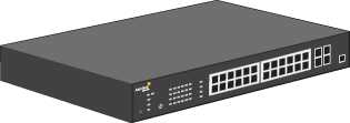
The SR2224P switch offers Gigabit Ethernet switching and advanced features that include static routing, user-based QoS, storm control, 802.1x multiple authentication for voice and data, as well as traditional switching features such as LLDP, Spanning Tree, and IGMP snooping. The SR2224P switch has 24 Ethernet PoE ports, 4x1 Gbps SFP uplink ports and one RJ45 Console port.
For information about how to connect your switch to the network, and for information about Extreme Networks switches in general, see Introduction to Extreme Switches
The information in this section applies to all Extreme Networks switch models. The following safety icons identify the type of precaution.

|
This icon indicates a general caution. Failure to comply with a caution notification can result in damage to equipment. |

|
This icon indicates an electrical caution. Failure to comply with an electrical notification can result in serious injury or death, and extensive damage to equipment. |

|
This icon indicates a laser caution. Failure to comply with a laser caution can result in serious injury. |
The following safety precautions apply to Extreme Networks switches:
|
|
Do not install the device in an environment where the operating ambient temperature might exceed the recommended ranges. |
|
|
Make sure the air flow for rack mounted devices is not restricted. |
|
|
Changes or modifications made to this device that are not expressly approved by the party responsible for compliance could void the user's authority to operate the equipment. |
|
|
The procedures in this manual are for qualified service personnel. |
|
|
Electrostatic discharge (ESD) can damage equipment and impair electrical circuitry. ESD damage occurs when electronic components are improperly handled and can result in complete or intermittent failures. Always follow ESD-prevention procedures when handling electronic components. |
|
|
Make sure the rack or cabinet housing the device is adequately secured to prevent it from becoming unstable or falling over. |
|
|
Disconnect the power cord from all power sources to completely remove power from the device. |
|
|
If the installation requires a different power cord than the one supplied with the device, make sure you use a power cord displaying the mark of the safety agency that defines the regulations for power cords in your country. The mark is your assurance that the power cord can be used safely with the device. |
|
|
The switch must be connected only to PoE networks without routing to the outside plant. |
|
|
All fiber optic interfaces contain Class 1 lasers. Invisible laser radiation can also be emitted from disconnected fibers. Never look into the end of a fiber, regardless of whether it is active or disconnected. |
|
|
The optical transceivers used in the SFP port must be laser class I components (under CDRH definition), compliant with IEC/EN60825. |

Note
Follow the safety guidelines in "Safety Guidelines " to ensure the safety of personnel and equipment.Install the SR2224P switch on a clean, level desktop or surface, or in a standard equipment rack using the rack mount kit that ships with the switch (see "Rack Mounting Instructions"). If you are installing your switch on a desktop or surface, attach the four rubber feet to the bottom of the chassis to provide stability and prevent the device from moving on the surface.
Shipping Carton Contents
The SR2224P ships with the following items:
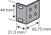
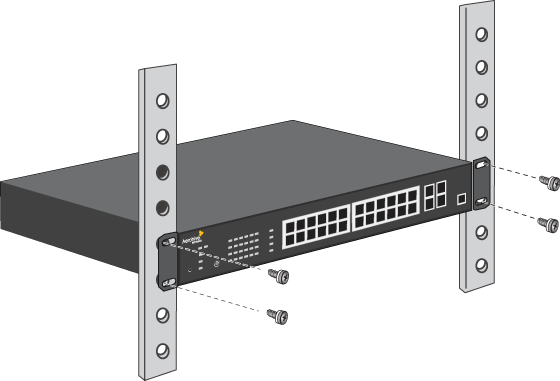
Use the procedures in this section to mount your device in a standard equipment rack.
|
|
For stability, always load a rack from the bottom to the top, with the heaviest devices on the bottom. A top-heavy rack is likely to be unstable and can tip over. |
Note
Adequate ventilation is critical for switch operation. Install your devices in a properly ventilated equipment rack, or for tabletop installations, leave 2 inches (5 cm) of clear space at the sides of the switch so the fans can properly cool the chassis.You can mount SR2224P switches in any standard 19" (48 cm) equipment rack. These devices require 1 rack unit (RU) of space, which is 1.75" (44.45 cm) high. Use the following steps to mount the switch in a rack.
You can see the hardware components for the SR2224P switch in the illustration below, and read about them in the descriptions that follow.
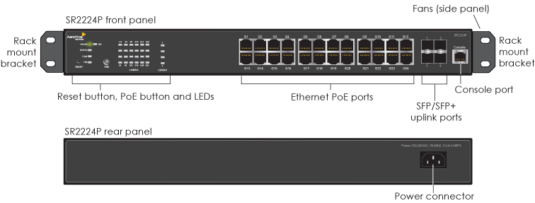
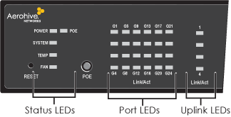
LED Panel
Status LEDs and Ethernet LEDs are located on the left side of the front panel. Uplink port LEDs appear between the ports on the right side of the panel. For descriptions of the LEDs, see "Power, Ethernet Port, and SFP Port Status LEDs".
Reset Button
Use the Reset button to reboot the device or reinstate the default factory settings. Insert a paper clip or similar tool into the pinhole and press the button. To reboot the device, hold the button down between 1 and 5 seconds. To return the configuration to the default settings, hold the button down for 5 seconds or longer. When you release the button, the System LED goes dark as the system reboots, then turns amber while the firmware loads and the system performs a self-test. After the firmware has finished loading and the switch has connected to ExtremeCloud IQ, the System LED glows steady green.
PoE Button
The PoE button allows you to change the port LED modes between link status and PoE status. By default, the port LEDs are in link status (ACT) mode. Press the PoE button to see the PoE status for each port.
Ethernet Ports
SR2224P switches have 24 10/100/1000-Mbps Ethernet RJ45 LAN ports (ETH 1 through ETH 24). These ports are compatible with 10/100/100Base-T/TX and negotiate half and full duplex connections with the connecting device. The ports are auto-sensing and adjust to straight-through and crossover Ethernet cables automatically.
PoE/PoE+Ports
SR2224P switches offer PoE or PoE+ on all 24 Ethernet ports to power PDs (powered devices) such as VoIP phones, wireless access points, and network cameras. The ports are IEEE802.3af and IEEE802.3at PSE (power sourcing equipment) compliant, as described here:
802.3af is the default setting for all ports, but you can configure all 24 ports for PoE (803.2af) or 12 ports for 802.3at and 6 ports for 803.2af, as long as you do not exceed the PoE power budget (180 W).
To change the power setting, first add 803.2af and 802.3at PSE profiles to your network policy in ExtremeCloud IQ and assign them to ports as needed. You can change the profile at any time. For more information see "PoE Power Management".
The Ethernet port pin assignments use the TIA/EIA-568-B standard. The ports accept standard Cat3, Cat5, Cat5e, or Cat6 Ethernet cable, and autosensing capabilities allow the wiring termination in the Ethernet cable to be either straight-through or crossover.
Port Priority
By default, all ports have priority enabled, with a setting of low. There are three port priorities: low, high, and critical. If there is no priority setting applied to a port, or if multiple ports have the same priority, the switch gives the port with the lowest number the higher priority.
You can assign and change port priorities through the PSE port profiles that you create and assign to your network policies in ExtremeCloud IQ.
SFP Uplink Ports
For additional uplink capacity, the switch has four 1 Gbps uplink ports that accommodate SFP modules. SFP uplink ports are typically used for capacity planning, and to leverage the higher network bandwidth capabilities and speeds typically offered by SFP modules to connect to uplink devices such as broadband modems, routers, switches, or hubs. For information about installing, replacing, and maintaining SFP modules, see "SFP Module Maintenance".
You can order SFP modules from Extreme Networks, or purchase your own modules. For more information, contact your Extreme Networks representative.
Power Connector
The power connector allows you to connect the switch to a standard AC power source. Because the switch does not have an on/off switch, it automatically powers on when you connect it to a power source.
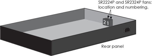
Fans
The cooling fans are located on the right side panel of the device (when facing the front panel).
Display Fan and Temperature Status using CLI Commands
To display the current status of the fans, enter the following command:
show system fans
To display the current system temperature, enter the following command:
show system temperature
View Fan and Temperature Status in ExtremeCloud IQ
To view fan and temperature status in ExtremeCloud IQ, navigate to Manage > Devices. Select the check box for a the name of a switch. A page appears that shows system information for the switch. Scroll down to the System Details section. The temperature and fan status appear at the bottom of this section.
The fans are numbered in order from front to back of the unit, as shown.
Console port
You can access the command line interface (CLI) for management and troubleshooting by making a serial connection to the RJ45 console port. The management station from which you connect to the device must have a VT100 emulation program, such as Tera Term Pro© (a free terminal emulator) or Hilgraeve Hyperterminal® (provided with Windows® operating systems from Windows 95 to Windows XP). The serial connection settings are: 9600 bits per second, 8 data bits, no parity, 1 stop bit, and no flow control.
For Console port pin assignments see Extreme Device Pin Assignments.
PoE Power Management
SR2224P switches support static and dynamic 802.3at/af PoE power management on all 24 ports. You can dedicate up to 12 ports for 802.3af, or 6 ports for 802.3at, as long as you do not exceed the power budget of 180 W.
When using dynamic power management (default), the switch measures the power consumption of each port in real time. If the power requirements exceed the PSE budget, the switch shuts down lower priority ports and transfers the power allotments to higher priority ports until the budget is met.
When using static power management, the maximum power delivered by each port is determined by the power threshold (802.3af or 802.3at) that is configured on that port. If more power is required than the ports can deliver, the switch shuts down lower priority ports and transfers their power allotment to higher priority ports.
The combined amount of power delivered by all ports cannot exceed the PSE power budget.
To change the power management setting in ExtremeCloud IQ, go to Manage > Devices. Select the check box for the switch, select  . In the Port Configuration page, under the device template, select the PSE tab. Configure the settings for each interface, and then select Save.
SFP Module Maintenance
Install or Replace an SFP Module
You can install or replace SFP modules in the switch while it is powered and running. When you are working with SFP modules, especially fiber modules, be aware of the following safety precautions:
|
|
All fiber optic interfaces contain Class 1 lasers. Invisible laser radiation can also be emitted from disconnected fibers. Never look into the end of a fiber, regardless of whether it is active or disconnected. |
|
|
Keep the chassis area clean and dust-free during and after installation. |
|
|
Electrostatic discharge (ESD) can damage equipment and impair electrical circuitry. ESD damage occurs when electronic components are improperly handled and can result in complete or intermittent failures. Be sure to follow ESD-prevention procedures when installing SFP modules. Wear an ESD wrist strap with a series 1 Megohm resistor and attach the clip end of the strap to a metal surface (such as an equipment rack) to act as ground. |
Follow these steps to install an SFP module:
Note
Always leave the protective cap in place on an SFP module when you are not using it to prevent dust from collecting on the connectors.Cable an SFP Module
To connect a cable to an SFP module, perform the following steps:
Note
Always clean cable and port connectors before cabling an SFP module. See "Cleaning Fiber Ports and Connectors" for information about how to clean fiber modules.Clean Fiber Ports and Connectors
To avoid problems with fiber optic connections, it is important to clean both cable and port connectors each time you connect or disconnect them. Dust accumulates easily in connectors and can cause connection problems.
Use a dry (recommended) or wet cleaning process to clean connectors using either lint-free wipes or lint-free swabs. Lightly wipe the connectors to clean them. Never reuse a wipe or swab. If possible, inspect the connectors with a fiber scope to check that they are properly clean.
If you use a wet cleaning process, use only 99% isopropyl alcohol. Make sure that all alcohol is wiped away from all surfaces (do not allow it to evaporate slowly) and has not collected in crevices of cavities. Alcohol residue can contaminate connectors and it is difficult to remove all traces of it. For this reason, a dry cleaning process is preferable.
Power, Ethernet Port, and SFP Port Status LEDs
The status LEDs on the switch front panel indicate activity states by color and illumination pattern. The following tables explain the LED activity for all LEDs.
System LEDs
| LED Type | Behavior |
|---|---|
| POWER |
Solid Green: Power is on. Dark: Power is off. |
| SYSTEM |
Solid Green: System is on and ready Off: Fault detected. |
| PoE |
Solid Amber: The switch is providing more than 80% of the power budget. Off: The switch is providing less than 80% of the power budget. |
| FAN |
Off: Fans are operating properly. Solid Red: Fans are not operating properly. |
Port LEDs
| Port LED | Behavior |
|---|---|
| Port Combo Link/PoE Status |
In Link Status Mode: Off: No link. Solid green: Link detected. Blinking green: Frames are being transmitted or received. In PoE Status Mode: Off: No PD detected. Solid green: 802.3af/at PD detected. |
| SFP/SFP+ |
Off: No link detected. Solid green: Link is detected. Blinking green: Frames are being transmitted or received. |
The following specifications describe the hardware components, electrical requirements, and the environmental ranges in which the SR2224P can operate.
Device and Enclosure Specifications
Power Specifications
Environmental Specifications
The regulatory compliance statements in this section apply to Extreme NetworksAP150W devices.
この装置は、クラスA情報技術装置です。この装置を家庭環境で使用すると電波妨害を引き起こすことがあります。この場合には使用者が適切な対策を講ずるよう要求されることがあります。 VCCI-A
Copyright © 2020 Extreme Networks. All rights reserved. Published March 2020.