Home > Hardware > ap > AP120 Hardware User Guide

|
AP120 Hardware User Guide
Read about and view specifications for the AP120 in this topic. Install the AP120 using this topic.
If your access point is configured for the World Regulatory Domain, it is important to set the country code to the country in which the AP will be deployed to meet regulatory requirements and for optimal wireless operation. To do this, follow these steps:

Note
The country code selection is for World models only and is not available to FCC, CAN, and other country-specific models. Per FCC regulations, all Wi-Fi products marketed in the United States must be set to U.S. channels only.For Devices Running HiveManager
For Devices Running HiveManager Classic
The AP120 has two radios—one for 802.11a/n and one for 802.11b/g/n, which can both operate concurrently. Both platforms provide 2x2:2 MIMO and a single 10/100/1000 Ethernet port through which they can be powered using PoE (power over Ethernet) that follows the IEEE 802.3af and 802.3at standards. Optionally, they can be powered by an AC/DC power adapter.
The AP120 contains a 2.4 GHz radio and a 5 GHz radio that can operate concurrently through four internal antennas. These devices support a variety of Wi-Fi security protocols, including WPA (Wi-Fi Protected Access) and WPA2.
For more information about Extreme Networks APs in general, see Introduction to Extreme APs
For information about connecting your AP to the network, best-practices, and troubleshooting, see Onboarding New Devices Troubleshooting Tips
For compliance information for these devices, see http://www.aerohive.com/support/tech-docs-and-online-training.
Safety Guidelines
The information in this section applies to AP120 devices.
The following safety icons are used in these guidelines to identify the type of precaution:

|
This icon indicates a general caution. Failure to comply with a caution notification can result in damage to equipment. |

|
This icon indicates an electrical caution. Failure to comply with an electrical notification can result in serious injury or death, and extensive damage to equipment. |

|
This icon indicates a laser caution. Failure to comply with a laser caution can result in serious injury. |
| The following table lists the safety precautions you should follow when installing your AP appliance. | |
|
|
Extreme Networks devices must be installed by a professional installer who is certified to install these types of devices and to ensure that they are properly grounded and meet applicable local and national electrical codes. |
|
|
These devices are intended for indoor use only. |
|
|
Do not install the device in an environment where the operating ambient temperature might exceed the recommended ranges. |
|
|
Electrical equipment generates heat. Ambient air temperature may not be adequate to cool equipment to acceptable operating temperatures without adequate circulation. Be sure that the room where you install your device has adequate air circulation. |
|
|
Changes or modifications made to this device that are not expressly approved by the party responsible for compliance could void the user's authority to operate the equipment. |
|
|
Electrostatic discharge (ESD) can damage equipment and impair electrical circuitry. ESD damage occurs when electronic components are improperly handled and can result in complete or intermittent failures. Be sure to follow ESD-prevention procedures when handling electronic components and equipment. |
|
|
Disconnect all power by turning off the power switch and unplugging the power cord before installing or removing a device, or working near power supplies. |
|
|
Never assume that power is disconnected from a circuit; always check the circuit. |
|
|
Explosion risk - There is a risk of an explosion if the lithium battery (for the CMOS clock) is replaced with an incompatible battery type. Battery replacement should be performed only by a trained electrician or technician who is able to understand all installation and device specifications. |
|
|
Lithium battery disposal - Regulations and laws pertaining to the recycling and disposal of lithium ion batteries vary from country to country as well as by state and local governments. European governments have more strict regulations on the disposal of rechargeable batteries than the USA and Canada. Check the laws and regulations where you live before disposing of lithium batteries. |
|
|
To meet federal radiation exposure requirements, these devices should be installed at a minimum distance of 9.05" (23 cm) from your body. |
Using the mounting plate and track clip, you can mount the AP120 to the tracks of a dropped ceiling grid. Using just the mounting plate, you can mount the AP to any surface that can support its weight (1.75 lb. (0.8 kg). The following sections describe these installation methods.
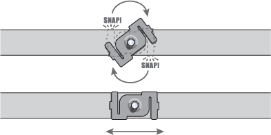
Ceiling Mount
To mount the AP120 to a track in a dropped ceiling, use the appropriate track clip for the width of the ceiling track. Two clips ship with the AP; one for 1" (2.54 cm) tracks and one for 1/2" (1.27 cm) tracks. Use the following steps:
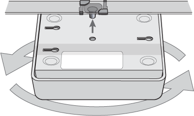
You can also mount the AP to a solid ceiling - or the underside of any horizontal object such as a crossbeam - using three #6 or #8 screws. Position the three screws in a T-shaped layout: two screws 2" (5 cm) apart from each other and the third screw center-aligned between them and 4.75" (12 cm) away. Then attach the AP to the screws as explained in the "Surface Mount" section, below.
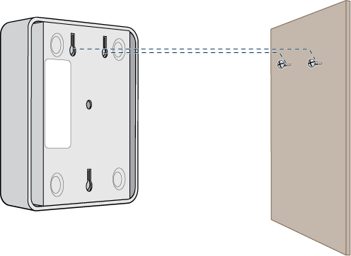
Surface Mount
You can attach an AP120 to any flat surface that supports its weight (1.75 lb. or 0.8 kg). Use the following steps.
You can use a Kensington® lock to secure the AP to a stationary object. See "Lock the AP120".
Lock the AP120
To lock the AP to a secure object, use a Kensington lock and cable. Loop the cable around a securely anchored object such as a support beam, then insert the T-bar component of the lock into the lock slot on the device. Turn the key to engage the locking mechanism.
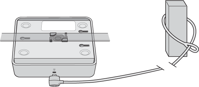
Extreme Networks recommends a variety of Kensington locks. For more information, contact your sales representative.
Hardware Components
You can see the hardware components for both models in the following illustration, and read about them in the descriptions that follow.
Note
To meet federal radiation exposure requirements, these devices should be installed at a minimum distance of 9.05" (23 cm) from your body.
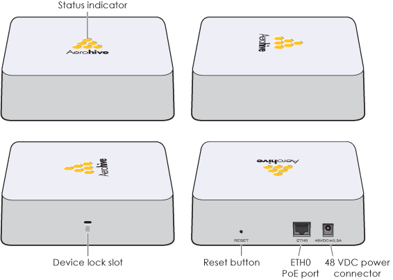
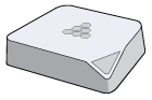
Status Indicator
The status indicator has been incorporated into the Extreme Networkslogo on the top of the AP110and AP120. It is illuminated by various colors to indicate different states of activity. The meanings of the colors are as follows:
You can adjust the brightness level from bright (the default) to soft to dim, or turn it off completely in ExtremeCloud IQ. Navigate to Configure > Network Policy > Additional Settings > Network Service > Management Options. Turn Management Options on and scroll down to the System Settingssection. Use the LED brightness drop-down box to select the brightness level that you want.
Note
When you change the brightness setting here, the new setting will apply to all devices under this network policy. To change the LED brightness for a single device, establish a console connection and use the CLI command.To turn the LED on or off or change the brightness using the CLI, enter:
system led brightness [ soft | dim | off ].
For devices running HM Classic, you can set the LEDs for all APs on your network to blink or remain steady. Navigate toHome > Device Management Settings > LED Mode.
Device Lock Slot
Device Lock Slot: You can physically secure the AP by attaching a lock and cable (such as a Kensington[(r)] notebook lock) to the device lock slot. See "Lock the AP120".
Power Connector
The 48-volt DC power connector (0.3 amps), with a voltage range of 36 to 57 volts DC, is one of two methods through which you can power the AP (the other is PoE). To connect it to a 100 – 240-volt AC power source, use the AC/DC power adapter (available as an extra accessory). Because the AP does not have an on/off switch, connecting it to a power source automatically powers on the device.
Antennas
The AP120 has four internal single-band antennas. Two of the antennas operate in the 2.4 GHz band (IEEE 802.11b/g/n) and have a 0-dBi gain. The other two antennas operate in the 5 GHz band (IEEE 802.11a/n) and have a 3-dBi gain. All antennas are omnidirectional, providing fairly equal coverage in all directions in a cardioid (heart-shaped) pattern around each antenna (see Antennas).
The two 2.4-GHz antennas link to one radio, and the two 5-GHz antennas link to the other radio, both of which can operate concurrently. Conceptually, the relationship of antennas and radios is shown in the following illustration.
Ethernet Port
The AP can receive power through an Ethernet connection to the ETH0 port from PSE (power sourcing equipment) that is compatible with the 802.3af and 802.3at standards. Extreme Networks provides suitable PoE injectors as an optional accessory.
Note
If you connect the AP to a power source using the power connector and the PoE port at the same time, the AP draws power through the power connector and automatically disables PoE.The ETH0 port is compatible with 10/100/1000Base-T/TX and automatically negotiates half- and full-duplex connections with the connecting device. It is autosensing and adjusts to straight-through and crossover Ethernet cables automatically. The port accepts standard Cat3, Cat5, Cat5e, and Cat6 Ethernet cable and can receive power over the Ethernet cable from power sourcing equipment (sec) that is 802.3af-compatible. If you use cat5, cat5e, or cat6 cables, the ETH0 port can also support 802.3at-compliant PSE. Such equipment can be embedded in a switch or router, or it can come from purpose-built devices that inject power into the Ethernet line en route to the AP. Because the PoE port has autosensing capabilities, the wiring termination in the Ethernet cable can be either straight-through or crossover. The pin assignments for the PoE port follow the TIA/EIA-568-B standard (see Extreme Device Pin Assignments).
Reset Button
You can reset the device or return it to the factory setting using the Reset button. Insert a paper clip or similar tool into the pinhole and press the button. To reboot the device, hold the button down between 1 and 5 seconds. To return the configuration to the factory default settings, hold it down for at least 5 seconds. After releasing the button, the status indicator goes dark as the system reboots. Then it glows blue while the device boots and the system performs a self-test. After the firmware finishes loading and the AP is ready to serve clients, the status indicator glows white.
To prevent the Reset button from resetting the configuration, enter this command: no reset-button reset-config-enable. Pressing the button between 1 and 5 seconds will still reboot the AP, but pressing it for more than 5 seconds will not reset its configuration.
The following specifications describe the physical features and hardware components, the power adapter and PoE electrical requirements, and the temperature and humidity ranges in which the device can operate.
Device Specifications
Power Specifications
Environmental Specifications
Copyright © 2020 Extreme Networks. All rights reserved. Published March 2020.