Router Mode Standard Deployment
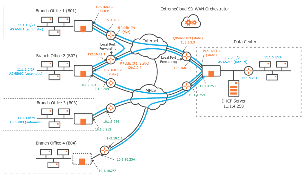
This section describes the main steps for configuring a Router Mode network. It is based on a typical use case illustrating a simple deployment where three branch office appliances are connected to a Data Center appliance over either the MPLS private network, or the Internet, or both. This deployment consists of configuring the appliances and creating IPsec tunnels.
A full Router Mode network includes appliances with WAN interfaces deployed in Router mode only. The SD-WAN Orchestrator enables you to build an overlay network of site connections through IPsec tunnels.
| • | B01 is connected to the Data Center through one tunnel over the Internet. Another tunnel connects B01 to B02. |
| • | B02 is connected to the Data Center through two tunnels, one over the Internet and the other one over MPLS. A third tunnel connects B02 to B01. |
| • | B03 is connected to the Data Center through one tunnel over the MPLS private network. |
| • | B04 is a RVC destination managed by remote appliances; there is a tunnel from the B04 CE router to the Data Center appliance. |
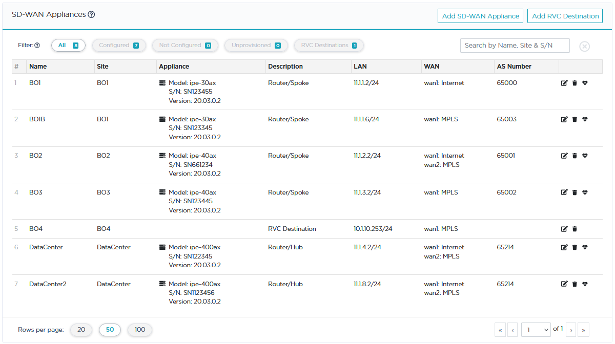
"Configuring the Data Center appliance"
"Configuring the Branch Office appliances"
Graph legend
|
|
|

|
|
|
|
Blue connection |
Grey connection |
|
SD-WAN appliance |
router |
RVC destination |
subnet |
host in a subnet |
server |
IPsec tunnel |
physical connection between devices |


Note: A router may be a CE Router (MPLS Router), an Internet Access Router or a Core Router.
Configuring the appliances
Refer to "Configuring the appliances" in the Hybrid Mode Standard Deployment section.