Configuring a multi-appliance Hybrid Data Center through OSPF
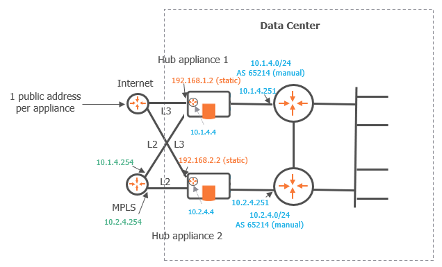
This deployment describes how to configure a Data Center with two appliances through OSPF. The objectives of this deployment is high availability: if one hub appliance is in bad health, the other appliance is used as backup appliance. It is complementary to "Use Case 1".
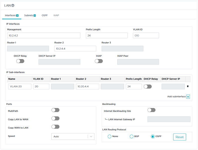
This configuration is done on the LAN panel of each appliance.
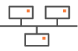
Graph legend
|
|
|
|
|
|
Grey connection |
|
SD-WAN appliance |
router |
subnet |
host in a subnet |
server |
connection between devices |


Note: A router may be a CE Router (MPLS Router), an Internet Access Router or a Core Router.
As you already configured the Data Center first hub appliance in Use Case 1, refer to "Configuring the LAN".
There is one prerequisite which is the necessary configuration of the second hub appliance of the Data Center.
Data Center second hub appliance
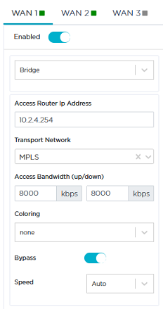
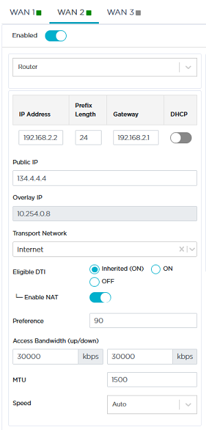
| 1 | Identify and configure the hub appliance WANs as follows: |

|
|
|
| 2 | Then configure its LAN. In the Interfaces window, select OSPF as the LAN Routing Protocol. |
| 3 | Click the Add subinterface icon |
| 4 | Click the OSPF tab. |
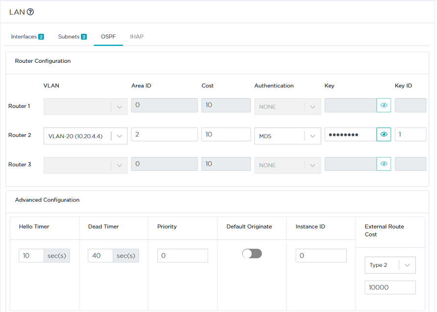
| 5 | Configure Router 2 as explained in "Configuring OSPF" for the Data Center first hub appliance. |
Enter 2 in the Area ID field.
| 6 | In the Advanced Configuration panel, define the External Route Cost specific parameter which implements the high availability mechanism between the two Data Center appliances. |
An external route corresponds to the traffic received by the appliance from the overlay.
| • | Type 1: the Metric value and the Cost of each link are taken into account to route the traffic. |
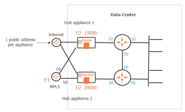
Cost: this parameter must be configured on your personal routers. The following image illustrates a consistent configuration of link costs. Note that a low cost has the priority over a higher cost.
Metric value: this value corresponds to a distance. The lowest value is the best one for routing the traffic.
To summarize Type 1 procedure, configure the MPLS CE router as E1. Then, adjust interface costs on your customer routers.
| • | Type 2: only the Metric value (distance) is taken into account. Set a E2 lower metric value on the Master appliance than on the Backup appliance. |
For the second appliance of the current Use Case, select Type 2 and enter 20000 as the Metric value.
Note: Type 1 takes priority over Type 2.
Data Center first hub appliance
| 7 | Execute the same configuration as described in the previous step. |
| 8 | In the External Route Cost fields, check that you selected Type 2 and entered 10000 as the Metric value. |
Since only the Metric values are taken into account for both Data Center appliances (Type 2), the first hub appliance with the lowest value is the Master whereas the second hub appliance is the Backup.
| 9 | Click Update. |