AP-8163 two radio models (AP-8163-66S40-US and AP-8163-66S40-WR) are configured with six N type connectors to support two active WLAN data radios.
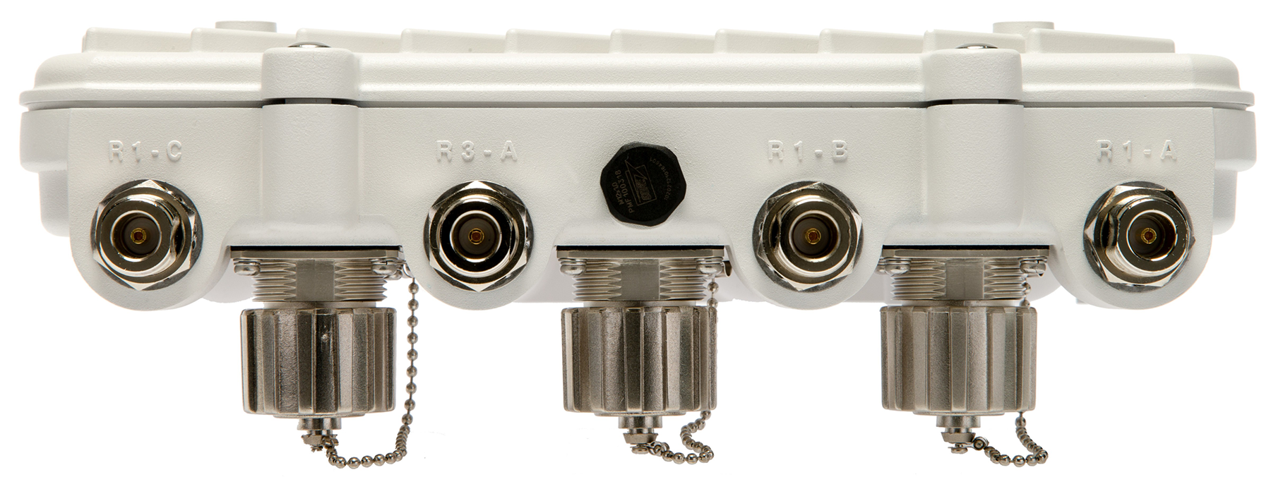
When mounting antennas to ports R1-A, R1-B, and R1-C, ensure you have selected the appropriate band for the configured radio that uses ports R1-A, R1-B, and R1-C. In this instance, R1 ports relate to the software configured radio 1 settings.
When mounting antennas to connectors marked R2-A, R2-B and R2-C, these antenna ports relate to the software settings of radio 2. Care must be taken to provide the correct antenna for the operating band of each port.
AP-8163 three radio models (AP-8163-66S40-US and AP-8163-66S40-WR) are configured with eight N type connectors to support two active WLAN data radios and a dedicated sensor radio as the third.
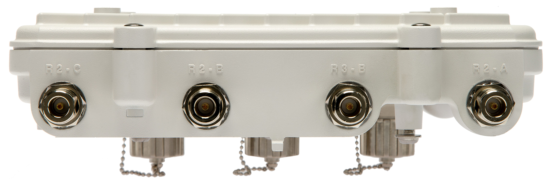
As with the two radio models, R1 ports relate to the software configured radio 1 settings. When mounting antennas to connectors marked R2-A, R2-B and R2-C, the antenna ports relate to the software configured radio 2 settings. Care must be taken to provide the correct antenna for the operating band of each port.
Ports R3-A and R3-B are reserved for the sensor radio. An appropriate multi band antenna should be mounted on the unit for sensor operation.

Note
The sensor radio does not function as a WLAN data radio.
Warning
Antenna ports where no antenna is mounted must be properly terminated using an approved IP67 terminator.Warning
All antenna connectors should be covered with weatherproofing tape. Print
this page
Print
this page Email this topic
 Feedback
 View PDF
 Download EPUB