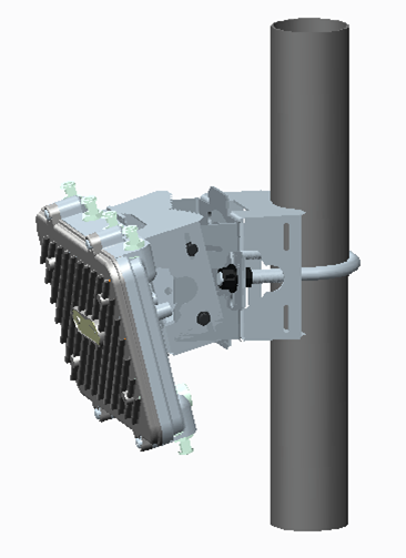
Installating the AP on a Pole
The mounting hardware kit and extension arm can be used in various
combinations to properly install the AP-8163 on a pole. For poles of up to 3 inches
in diameter, attach the pole mount bracket of the mounting hardware kit at the
desired position on the pole using band clamps up to 3/4 inch width, or a 1/2 inch x
4 inch wide U-bolt and nuts. For poles greater than 3 inches in diameter, attach the
pole mount bracket using band clamps.

Caution
Always mount the AP-8163
with the black gore vent facing down.

Note
The U-bolt and band clamps are
not included in the mounting bracket kit.
Note
Use of the extension arm
is recommended for installations on poles greater than 3 inches in
diameter.
Vertical Pole Mount
Use the following procedure for vertical pole mount installations. The extension arm
is recommended when mounting the Access Point to poles greater than 3 inches is
diameter.
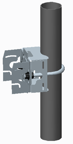
For poles up to 3 inches in diameter when using a U-bolt:
- Thread two 1/2 inch nuts onto the U-bolt.
- Position the U-bolt on the pole and place the pole mount bracket section on the
U bolt. Adjust the two 1/2 inch inner nuts until the pole mount bracket section
is against the pole and the U-bolt can be secured tightly to the pole at the
desired mounting location.
Mounting Harware Pole Ubolt 1
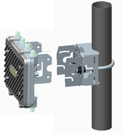
- Place the angle adapter bracket section on the U-bolt with the open slot
connections on the bottom and align it with the pole mount section. Attach with
two 1/2 inch nuts. Tighten all nuts to 300 inch pounds (lbf-in).
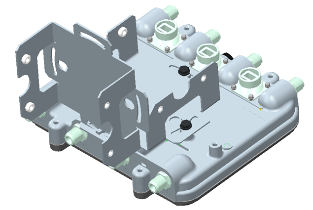
- Position the Access Point bracket section so the bottom of the section with the
straight (not bevel cut) side is oriented toward the bottom side of the AP with
the gore vent. Using a torque wrench or a ratchet and a 10mm socket, or an
adjustable wrench, attach (but don‘t tighten) the Access Point bracket section
to the AP-8163 with the four M6 flange screw.
AP-8163 Mounting Hardware Bracket (Horizontal)
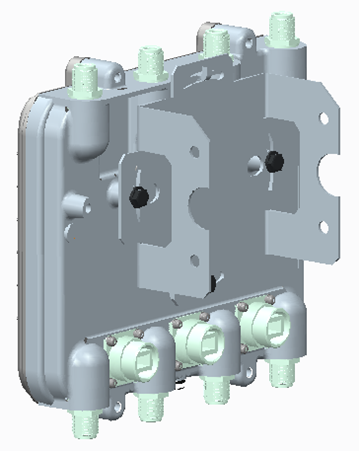
- Insert two M6 hex flange screws into the bottom holes on the sides of the
Access Point bracket section.
AP-8163 Mounting Hardware Bracket (Vertical)
- With the Access Point positioned so the gore vent is facing down, insert the
two M6 hex flange screws in the bottom holes on the sides of the Access Point
bracket section into the open slot connections on the bottom of the angle
adapter bracket section.
- Rotate the Access Point bracket section upward and align the top holes on the
sides with the top holes on the angle adapter bracket section. Insert two M6 hex
flange screws into the top holes on the angle adapter bracket section.
- Use a torque wrench or a ratchet and a 10mm socket, or an adjustable wrench, to
finish attaching the Access Point bracket section to the angle adapter bracket
section with the M6 hex flange screws in the open slot connections and the top
holes on the angle adapter bracket section. Do not tighten the screws until all
rotation and tilt adjustments are complete.
- To adjust the position of the Access Point, rotate the Access Point bracket
section (plus or minus 15 degrees) and tilt the angle adapter bracket section
(up to 45 degrees).
- Tighten all hex flange screws to 60 inch pounds (lbf-in).
 Print
this page
Print
this page Email this topic
 Feedback
 View PDF
 Download EPUB