An access point can have its radio profile configuration overridden after its radios have successfully associated to the network.
To define an access point's radio configuration:
| Name |
Displays whether the reporting radio is radio 1, radio 2 or radio 3. AP 6522, AP 6522M, AP 6532, AP 6562, AP 8132, AP 8232, AP 7161, and AP 7181 models have 2 radios. |
| Type | Displays whether the radio has been designated as a typical WLAN radio or if the radio has been designated as a sensor. |
| Description | A brief description provided by the administrator when the radio's configuration was added or modified. |
| Admin Status | A green check mark means the radio is enabled for client or sensor support. A red “X” means the radio is currently disabled. |
| RF Mode | Displays whether each listed radio is operating in the 802.11a/n or 802.11b/g/n radio band. If the radio is a dedicated sensor, it will be listed as a sensor to define the radio as not providing typical WLAN support. If the radio is a client bridge, it provides a typical bridging function and does not provide WLAN support. The radio band is set in the Radio Settings tab. |
| Channel | Lists the channel setting for the radio. Smart is the default setting. If set to Smart, the access point scans non-overlapping channels listening for beacons from other access points. After the channels are scanned, it selects the channel with the fewest access points. In the case of multiple access points on the same channel, it selects the channel with the lowest average power level. |
| Transmit Power |
Lists the transmit power for each radio. The column displays smart if Smart-RF is used to set the transmit power for this radio. |
| Overrides |
Click Clear to clear overrides made to this radio interface. This field is blank if there are no overrides for this radio. |
| Description | Provide or edit a description (1 - 64 characters in length) for the radio that helps differentiate it from others with similar configurations. |
| Admin Status |
Select Active or Shutdown to define this radio‘s availability. When defined as Active, the access point is operational and available for client support, Shutdown renders it unavailable. |
| Radio QoS Policy | Use the drop-down menu to specify an existing QoS policy to apply to the access point radio in respect to its intended radio traffic. If no existing policy is suitable for this radio‘s intended operation, select the Create icon to define a new QoS policy. |
| Association ACL |
Specify an existing Association ACL policy to apply to the radio. An Association ACL is a policy-based Access Control List (ACL) that either prevents or allows wireless clients from connecting to an access point radio. An ACL is a sequential collection of permit and deny conditions that apply to packets. When a packet is received on an interface, the fields in the packet are compared to applied ACLs to verify the packet has the required permissions needed to be forwarded. If a packet does not meet any of the ACL criteria, the packet is dropped. Select the Create icon to define a new Association ACL. |

Note
Most access point models can support up to 256 clients per access point or radio.| RF Mode |
Set the mode to either 2.4 GHz WLAN or 5.0 GHz WLAN depending on the radio‘s intended client support. Set the mode to sensor if you are using the radio for rogue device detection. Set the mode to client-bridge to configure the radio as a client bridge. A client bridge enables the access point to connect to a third party access point and bridge frames to it. |
| Lock RF Mode | Select this option to lock Smart RF calibration functions for this radio. The default setting is disabled. |
| Channel | Select the channel of operation
for the radio. Only a trained installation professional
should define the radio channel. Select Smart for
the radio to scan non-overlapping channels to listen for
beacons from other access points. After channels are
scanned, the radio selects the channel with the fewest
access points. In case of multiple access points on the same
channel, it selects the channel with the lowest average
power level. The default value is Smart. Channels with a “w” appended to them are unique to the 40 MHz band. |
| DFS Revert Home |
Select this option to enable a radio to return to its original channel. Dynamic Frequency Selection (DFS) prevents a radio from operating in a channel where radar signals are present. When radar signals are detected in a channel, the radio changes its channel of operation to another channel. The radio cannot use the channel it has moved from for the next 30 minutes. When DFS Revert Home is selected, the radio can return back to its original channel of operation when the 30-minute period is over. When not selected, the radio cannot return back to its original channel of operation ever after the mandatory 30-minute evacuation period is over. |
| Transmit Power | Set the transmit power of the
selected access point radio. If the access point has two
radios, each radio should be configured with a unique
transmit power in respect to its intended client support
function. Select smart to use Smart RF to determine output power. smart is the default value. |
| Antenna Gain | Set the antenna between 0.00 - 15.00 dBm. The access point‘s Power Management Antenna Configuration File (PMACF) automatically configures the access point‘s radio transmit power based on the antenna type, its antenna gain (provided here) and the deployed country‘s regulatory domain restrictions. Once provided, the access point calculates the power range. Antenna gain relates the intensity of an antenna in a given direction to the intensity that would be produced ideally by an antenna that radiates equally in all directions (isotropically), and has no losses. Although the gain of an antenna is directly related to its directivity, its gain is a measure that takes into account the efficiency of the antenna as well as its directional capabilities. Only a professional installer should set the antenna gain. The default value is 0.00. |
| Antenna Mode | Set the number of transmit and receive antennas on the Access Point. 1x1 is used for transmissions over just the single “A” antenna, 1x3 is used for transmissions over the “A” antenna and all three antennas for receiving. 2x2 is used for transmissions and receipts over two antennas for dual antenna models. The default setting is dynamic, based on the access point model and its transmit power settings. |
| Enable Antenna Diversity |
Select this option for the radio to dynamically change the number of transmit chains. This option is enabled by default. |
| Adaptivity Recovery | Select this option to switch channels when an access point‘s radio is in adaptivity mode. In adaptivity mode, an access point monitors interference on its set channel and stops functioning when the radio‘s defined interference tolerance level is exceeded. When the defined adaptivity timeout is exceeded, the radio resumes functionality on a different channel. This option is enabled by default. |
| Adaptivity Timeout | Set the adaptivity timeout from 30 to 3,600 minutes. The default setting is 90 minutes. |
| Wireless Client Power | Select this option to enable a spinner control for client radio power transmissions in dBm. The available range is 0 - 20 dBm. |
| Dynamic Chain Selection | Select this option to allow the access point radio to dynamically change the number of transmit chains. The radio uses a single chain/antenna for frames at non 802.11n data rates. This setting is disabled by default. |
| Rate |
Once the radio band is provided, the Rate drop-down menu populates with rate options depending on the 2.4 or 5.0 GHz band selected. If the radio band is set to Sensor or Detector, the Data Rates drop-down menu is not enabled, as the rates are fixed and not user configurable. If 2.4 GHz is selected as the radio band, select separate 802.11b, 802.11g and 802.11n rates and define how they are used in combination. If 5.0 GHz is selected as the radio band, select separate 802.11a and 802.11n rates define how they are used together. When using 802.11n (in either the 2.4 or 5.0 GHz band), Set a MCS (modulation and coding scheme) in respect to the radio‘s channel width and guard interval. An MCS defines (based on RF channel conditions) an optimal combination of 8 data rates, bonded channels, multiple spatial streams, different guard intervals, and modulation types. Clients can associate as long as they support basic MCS (as well as non-11n basic rates). For more information on 802.11n MCS rates, see “MCS Data Rates". |
| Radio Placement | Specify whether the radio is located Indoors or Outdoors. The placement should depend on the country of operation selected and its regulatory domain requirements for radio emissions. The default setting is Indoors. |
| Max Clients | Set the maximum permissible client connections for this radio. Set a value from 0 - 256. Most access point models can support up to 256 clients per access point or radio. |
| Rate Selection Methods |
Specify the algorithm to use for rate selection. Select Standard to use the standard rate selection algorithm. Select Opportunistic to use the Opportunistic rate selection algorithm. |
| Beacon Interval | Set the interval between radio beacons in milliseconds (either 50, 100 or 200). A beacon is a packet broadcast by adopted radios to keep the network synchronized. Included in a beacon is the WLAN service area, radio address, broadcast destination addresses, a time stamp, and indicators about traffic and delivery (such as a DTIM). Increase the DTIM/ beacon settings (lengthening the time) to let nodes sleep longer and preserve battery life. Decrease these settings (shortening the time) to support streaming-multicast audio and video applications that are jittersensitive. The default value is 100 milliseconds. |
| DTIM Interval | Set a DTIM Interval to specify a period for Delivery Traffic Indication Messages (DTIM). A DTIM is periodically included in a beacon frame transmitted from adopted radios. The DTIM indicates broadcast and multicast frames (buffered at the access point) are soon to arrive. These are simple data frames that require no acknowledgment, so nodes sometimes miss them. Increase the DTIM/ beacon settings (lengthening the time) to let nodes sleep longer and preserve their battery life. Decrease these settings (shortening the time) to support streaming multicast audio and video applications that are jitter-sensitive. |
| RTS Threshold | Specify a Request To Send (RTS)
threshold (from 1 - 65,536 bytes) for use by the WLAN's
adopted access point radios. RTS is a transmitting station's
signal that requests a Clear To
Send (CTS) response from a receiving client. This
RTS/CTS procedure clears the air where clients are
contending for transmission time. Benefits include fewer
data collisions and better communication with nodes that are
hard to find (or hidden) because of other active nodes in
the transmission path. The default value is 65,536 bytes.
Control RTS/CTS by setting an RTS threshold. This setting initiates an RTS/ CTS exchange for data frames larger than the threshold, and sends (without RTS/CTS) any data frames smaller than the threshold. Consider the tradeoffs when setting an appropriate RTS threshold for the WLAN's access point radios. A lower RTS threshold causes more frequent RTS/CTS exchanges. This consumes more bandwidth because of additional latency (RTS/CTS exchanges) before transmissions can commence. A disadvantage is the reduction in data-frame throughput. An advantage is quicker system recovery from electromagnetic interference and data collisions. Environments with more wireless traffic and contention for transmission make the best use of a lower RTS threshold. A higher RTS threshold minimizes RTS/CTS exchanges, consuming less bandwidth for data transmissions. A disadvantage is less help to nodes that encounter interference and collisions. An advantage is faster data-frame throughput. Environments with less wireless traffic and contention for transmission make the best use of a higher RTS threshold. |
| Short Preamble | If you are using an 802.11bg radio, select this option for the radio to transmit using a short preamble. Short preambles improve throughput. However, some devices (SpectraLink phones) require long preambles. This option is disabled by default. |
| Guard Interval | Specify a Long or Any guard interval. The guard interval is the space between characters being transmitted. The guard interval eliminates inter-symbol interference (ISI). ISI occurs when echoes or reflections from one character interfere with another character. Adding time between transmissions allows echo's and reflections to settle before the next character is transmitted. A shorter guard interval results in shorter character times which reduces overhead and increases data rates by up to 10%. The default value is Long. |
| Probe Response Rate | Specify the data rate used for the transmission of probe responses. Options include highest-basic, lowest-basic, and follow-probe-request. The default value is follow-probe-request. |
| Probe Response Retry | Select this option to retry probe responses if they are not acknowledged by the target wireless client. This option is enabled by default. |
| Mesh | Set the mesh mode for this radio – either Client, Portal, or Disabled. Select Client to scan for mesh portals, or nodes that have connection to portals, and connect through them. Portal operation begins beaconing immediately and accepts connections from other mesh supported nodes. In general, the portal is connected to the wired network. The default value is Disabled. |
| Mesh Links | Specify the number of mesh links (1 -6) an access point radio will attempt to create. The default setting is 3 links. |
| Mesh PSK | Use the field to define the shared key for mesh. From the drop-down, select the type of the key. Click Show to display the characters used in the key. |
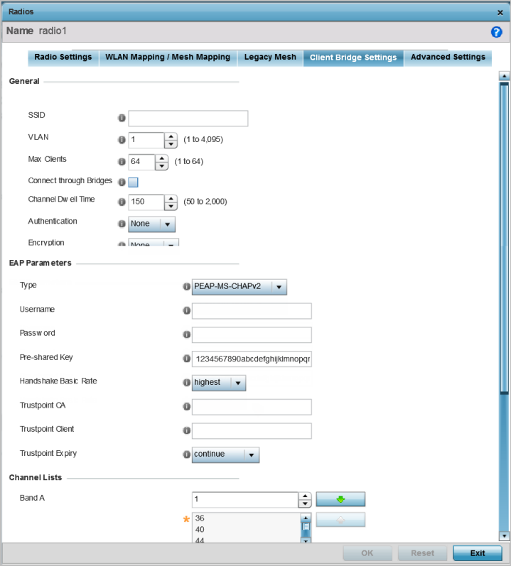
Note
Before configuring the client-bridge parameters, set the radio's rf-mode to bridge.An access point's radio can be configured to form a bridge between its wireless/wired clients and an infrastructure WLAN. The bridge radio authenticates and associates with an infrastructure WLAN Access Point. After successful association, the Access Point switches frames between its bridge radio and wired/wireless client(s) connected either to its GE port(s) or to the other radio, thereby providing the clients access to the infrastructure WLAN resources. This feature is supported only on the AP 6522, AP 6562, AP 7532, AP 7562, AP 7602, and AP 7622 model access points.
| A-MPDU Modes | Specify the A-MPDU mode. Options include Transmit Only, Receive Only, Transmit and Receive, and None. The default value is Transmit and Receive. Using the default value, long frames can be both sent and received (up to 64 KB). When this option is enabled, define a transmit limit, a receive limit, or both. |
| Minimum Gap Between Frames |
Specify the minimum gap between A-MPDU frames (in microseconds). The default value is auto, which indicates that the minimum gap between frames is selected automatically. The other values are 0, 1, 2, 4, 8, and 16. |
| Received Frame Size Limit | If a support mode is enabled allowing A-MPDU frames to be received, define an advertised maximum limit for received A-MPDU aggregated frames. Options include 8191, 16383, 32767, and 65535 bytes. The default value is 65535 bytes. |
| Transmit Frame Size Limit | Use the spinner control to set a
limit on transmitted A-MPDU aggregated frames. The available range is from 0 to 65535 bytes. The default value is 65535 bytes. |
| Forward | Select this option to enable forwarding of Aeroscout packets. |
| MAC to be forwarded | Enter the MAC address that is incorporated in the Aeroscout packets that are forwarded. |
| Forwarding Host | Specify the IP address of the host to which Ekahau packets are forwarded. |
| Forwarding Port | Set the Ekahau forwarding port number.. |
| MAC to be forwarded | Enter the MAC address that is incorporated in the Ekahau packets that are forwarded. |
| Non-Unicast Transmit Rate | Use the Select drop-down menu to launch a sub-screen to define the data rate for broadcast and multicast frame transmissions. If you are not using the same rate for each BSSID, seven different rates are available – each with a separate menu. |
| Non-Unicast Forwarding | Define whether client broadcast and multicast packets should always follow DTIM, or only follow DTIM when using Power Save Aware mode. The default setting is Follow DTIM. |
| Host for Redirected Packets | If packets are redirected from a controller or service platform‘s connected access point radio, specify the IP address of a resource (additional host system) used to capture the redirected packets. This address is the numerical (non DNS) address of the host used to capture the redirected packets. |
| Channel to Capture Packets | Specify the channel used to capture redirected packets. The default value is channel 1. |
| Enable Off-Channel Scan |
Select this option to scan across other channels in the radio band. This option is disabled by default. |
| Off Channel Scan list for 5GHz | Select the list of channels for off-channel scans using the access point's 5GHz radio. |
| Off Channel Scan list for 2.4GHz | Select the list of channels for off-channel scans using the access point's 2.4GHz radio. |
| Max Multicast | Set the maximum number (from 0 - 100) of multicast/broadcast messages used to perform off-channel scanning. |
| Scan Interval | Set the interval (from 2 - 100 dtims) between off-channel scans. |
| Sniffer Redirect | Specify the IP address of the host to which captured off-channel scan packets are redirected. |
| Enable Antenna Downtilt | Antenna Downtilt is used where there need to be a separation between the 2.4 GHz and 5.0 GHz bands. The 2.4 GHz band is tilted by 15 degrees (up/ down tilt) using software. Select to enable downtilt. |
| Extend Range | Select to enable extending the range of the access points. The access point uses various technologies to extend their service range. Use the spinner to set the range of service. Range can be 1 - 25 Kilometers. |
 Print
this page
Print
this page Email this topic
 Feedback
 View PDF
 Download EPUB