Home > Hardware > ap > AP330 and AP350 Hardware User Guide

|
AP330 and AP350 Hardware User Guide
Read about and view specifications for the AP330 and AP350 in this topic. Install the AP330 or AP350 using this topic.
If your access point is configured for the World Regulatory Domain, it is important to set the country code to the country in which the AP will be deployed to meet regulatory requirements and for optimal wireless operation. To do this, follow these steps:

Note
The country code selection is for World models only and is not available to FCC, CAN, and other country-specific models. Per FCC regulations, all Wi-Fi products marketed in the United States must be set to U.S. channels only.For Devices Running HiveManager
For Devices Running HiveManager Classic
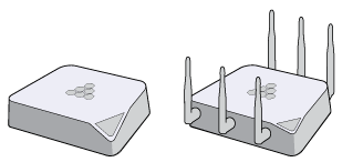
The AP330 and AP350 802.11n wireless access points are designed for greater throughput and range, and can also be configured as routers.
The AP330 and AP350 provide dual concurrent 802.11b/g/n and 802.11a/n radios for 3x3:3 MIMO antenna configurations. When you enable 802.11n high-throughput options such as wide-channel mode (40-MHz channels), A-MPDU and A-MSDU packet aggregation, short guard interval, and MCS23 data rates, these models can provide a PHY data rate of up to 450 Mbps per radio. The AP330 has internal antennas, and the AP350 uses detachable external antennas. Both models have dual 10/100/1000 Ethernet ports for link aggregation or link redundancy. They can accept power from an 802.3af or 802.3at standard PoE (power over Ethernet) power injector or from an AC/DC power adapter connected to a 100-240 VAC input power source.
For more information about Extreme Networks APs in general, see Introduction to Extreme APs
For information about connecting your AP to the network, best-practices, and troubleshooting, see Onboarding New Devices Troubleshooting Tips.
For compliance information for these devices, see http://www.aerohive.com/support/tech-docs-and-online-training.
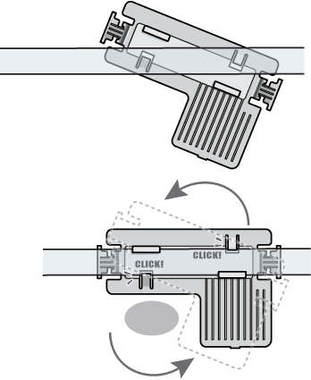
Using the mounting plate and track clip, you can mount the AP330 or AP350 to the tracks of a dropped ceiling grid. Using just the mounting plate, you can mount the AP to any surface that can support its weight (AP330: 1.5 lb., 0.6 kg; AP350: 2.38 lb., 1.08 kg).The following sections describe these installation methods.
Safety Guidelines
The information in this section applies to the AP330 and AP350 devices.
The following safety icons are used in these guidelines to identify the type of precaution:

|
This icon indicates a general caution. Failure to comply with a caution notification can result in damage to equipment. |

|
This icon indicates an electrical caution. Failure to comply with an electrical notification can result in serious injury or death, and extensive damage to equipment. |

|
This icon indicates a laser caution. Failure to comply with a laser caution can result in serious injury. |
General Cautions and Warnings
The following table lists the safety precautions you should follow when installing your AP330 and AP350 devices.
|
|
Extreme Networks devices must be installed by a professional installer who is certified to install these types of devices and to ensure that they are properly grounded and meet applicable local and national electrical codes. |
|
|
These devices are intended for indoor use only. |
|
|
These devices are intended for installation in accordance with the National Electric Code and local regulations in the United States or the Canadian Electrical Code and local regulations in Canada. |
|
|
Do not install the device in an environment where the operating ambient temperature might exceed the recommended ranges. |
|
|
Electrical equipment generates heat. Ambient air temperature may not be adequate to cool equipment to acceptable operating temperatures without adequate circulation. Be sure that the room where you install your device has adequate air circulation. |
|
|
Changes or modifications made to this device that are not expressly approved by the party responsible for compliance could void the user's authority to operate the equipment. |
|
|
These devices are not designed or approved for use with power lines other than 110-120 V or 220-240 volts, 50/60 Hz, single phase (depending on the country in which they are being used). Attempting to use these devices on non-approved power lines may have hazardous consequences. |
|
|
Do not plug these devices into a filtered power strip or AC line filter. |
|
|
Do not install these devices near large metal objects such as a refrigerator, filing cabinet, or television, as these objects may absorb radio frequency (RF) signals. |
|
|
These devices are not intended for use by persons (including children) with reduced physical, sensory, or mental capabilities, or with lack of experience of knowledge unless they are given supervision or instruction concerning use of the devices by a person who is responsible for their safety. Children should be supervised to ensure that they do not play with the devices. |
|
|
If the power cord is damaged, the AC adaptor should be disconnected from the main power source. |
|
|
Electrostatic discharge (ESD) can damage equipment and impair electrical circuitry. ESD damage occurs when electronic components are improperly handled and can result in complete or intermittent failures. Be sure to follow ESD-prevention procedures when handling electronic components. |
|
|
Disconnect all power by turning off the power switch and unplugging the power cord before installing or removing a device, or working near power supplies. |
|
|
Never assume that power is disconnected from a circuit; always check the circuit. |
|
|
Explosion risk - There is a risk of an explosion if the lithium battery (for the CMOS clock) is replaced with an incompatible battery type. Battery replacement should be performed only by a trained electrician or technician who is able to understand all installation and device specifications. |
|
|
Lithium battery disposal - Regulations and laws pertaining to the recycling and disposal of lithium ion batteries vary from country to country as well as by state and local governments. European governments have more strict regulations on the disposal of rechargeable batteries than the USA and Canada. Check the laws and regulations where you live before disposing of lithium batteries. |
|
|
To meet federal radiation exposure requirements, these devices should be installed at a minimum distance of 9.05" (23 cm) from people and animals. |
Cautions and Warnings for the Kingdom of Saudi Arabia
In addition to the general cautions and warnings shown above, the following cautions and warnings apply specifically to devices sold and installed in the Kingdom of Saudi Arabia:
|
|
These devices are designed and approved for use on 220-240 V, 50/60 Hz single phase power lines only. Attempting to use these devices on non-approved power lines may cause hazardous consequences. |
|
|
Do not install these devices near large metal objects such as a refrigerator, filing cabinet, or television, as these objects may absorb radio frequency (RF) signals. |
|
|
Do not plug these devices into a filtered power strip or AC line filter. |
|
|
Install these devices in different areas of your building, keeping them within communication range of each other. |
|
|
In multi-story buildings, install devices on different floors. |
|
|
These devices work best when installed in open areas. |
|
|
These devices are not intended for use by persons (including children) with reduced physical, sensory, or mental capabilities, or with lack of experience of knowledge unless they are given supervision or instruction concerning use of the devices by a person who is responsible for their safety. Children should be supervised to ensure that they do not play with the devices. |
|
|
Do not plug these devices into an outlet that is controlled by a switch. It the switch is inadvertently turned off, the device will not have power. |
Shipping Carton Contents
The AP330 and AP350 wireless access points shipping carton contain the following items:
2 security screws
2 cross-head screws
3 wall-mount screws with anchors
1 security bracket
4 adhesive rubber feet
Ceiling Mount
To mount the AP330 or AP350 to a track in a dropped ceiling, use one of the two rail mounts that ship with the product, depending on whether the ceiling track is flush with the ceiling tiles or recessed:
Surface Mount
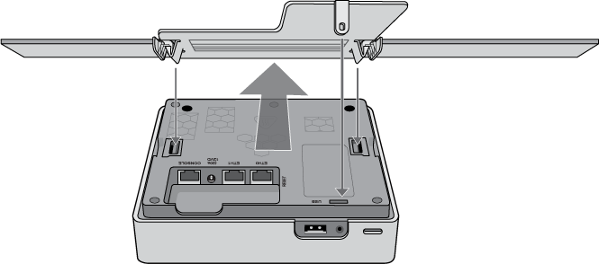
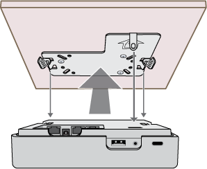
You can use the flat mounting plate to attach the AP330 or AP350 to any surface that supports its weight (AP330: 1.5 lb., 0.6 kg; AP350: 2.38 lb., 1.08 kg), and to which you can screw or nail the plate. Follow these steps:
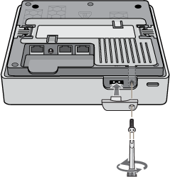
Lock the AP330 and AP350
To lock the AP to the rail mount bracket or wall mounting plate, use either a Kensington® lock or the security screw that is included with the mounting kit. To use a Kensington lock, loop the cable attached to the lock around a secure object, insert the T-bar component of the lock into the device lock slot on the AP, and then turn the key to engage the lock mechanism.
To lock the AP to the rail mounting bracket or mounting plate, you can use either the slotted screw or the pan-head security screw, both of which are included in the mounting kit. If you use the security screw, you will need a spanner insert bit for size #6 security screws and a driver handle that will accept the bit. The correct bits are available from Extreme Networks in sets of three for AP121, AP141, AP230, AP330, and AP350 models (AH-ACC-SEC-BIT-300-100-3PK). If you use the slotted screw, you can install it with a standard flat-blade screwdriver or pan-head driver bit.
Extreme Networks recommends a variety of Kensington[(r)] locks. For more information, contact your sales representative.
Hardware Components
You can see the hardware components for the AP330 and the AP350 in the following illustration, and read about them in the descriptions that follow.
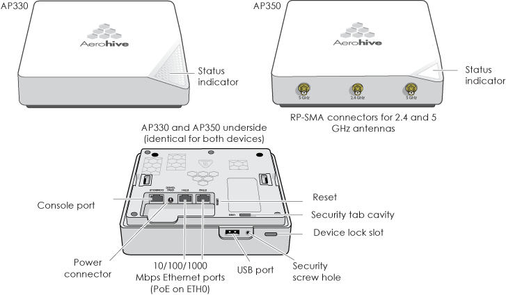
Status Light
The status light conveys operational states for system power, firmware updates, Ethernet and wireless interface activity, and major alarms. The AP330 and AP350 have a status light bar in the triangular region on the top surface. The illumination colors of this light indicate the following states of activity:
You can adjust the brightness level from bright (the default) to soft to dim, or turn it off completely in ExtremeCloud IQ. Navigate to Configure > Network Policy > Additional Settings > Network Service > Management Options. Turn Management Options on and scroll down to the System Settings section. Use the LED brightness drop-down to select the brightness level that you want.
Note
When you change the brightness setting here, the new setting will apply to all devices under this network policy. To change the LED brightness for a single device, establish a console connection and use the CLI command.To turn the LED on or off and select the level of brightness using the CLI, enter:
system led brightness [ bright | soft | dim | off ]
For devices running HM Classic, you can set the LEDs for all APs on your network to blink or remain steady. Navigate toHome > Device Management Settings > LED Mode.
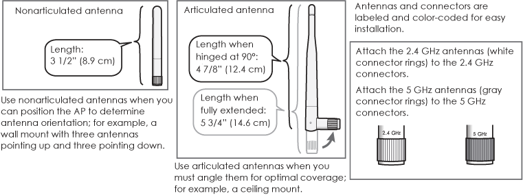
Antennas and Antenna Connectors
The AP330 has six internal single-band antennas. Three of the antennas operate in the 2.4 GHz band (IEEE 802.11b/g/n) with a 2-5 dBi gain. The other three antennas operate in the 5 GHz band (IEEE 802.11a/n) with a 3-6 dBi gain. All antennas are omnidirectional and provide fairly equal coverage in all directions.
The AP350 has six male 802.11a/b/g/n RP-SMA connectors for attaching up to six single-band dipole antennas. Articulated and non-articulated antennas are available as accessories. The articulated 2.4 GHz and 5 GHz antennas have a 4-dBi gain. The non-articulated 2.4 GHz and 5 GHz antennas have a 2-dBi gain. These antennas are omnidirectional, providing fairly equal coverage in all directions in a toroidal (donut-shaped) pattern. For greater coverage on a horizontal plane, it is best to orient the antennas vertically. So that you can easily do this whether the AP is mounted horizontally or vertically, the articulated antennas hinge and swivel. The non-articulated antennas are intended for wall installations and have a fixed orientation in the same direction as the antenna connectors.
Connect the 2.4 GHz and 5 GHz antennas to the connectors with the corresponding labels.
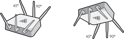
For optimal coverage, align the AP350 antennas as shown in the following illustration. The center antenna should be vertical and the side antennas slanted at 45° angles away from the center antenna.
For more information about configuring antennas for best coverage, see Antennas.
Console Port
Through the Console port, you can make a serial connection between your management system and the AP. When you connect to the device using the RJ45 Console port, the management station from which you connect to the device must have a VT100 emulation program, such as Tera Term Pro© (a free terminal emulator) or Hilgraeve HyperTerminal® (provided with Windows® operating systems from XP forward). The serial connection settings are: 9600 bits per second, 8 data bits, no parity, 1 stop bit, no flow control.
For the pin-to-signal mapping for the Console port see Extreme Device Pin Assignments.
Power Connector
There are two ways to power an AP330 or AP350. You can connect a device to a 100 – 240-volt AC power source by connecting an AC/DC power adapter to the 12 V (1.1A) DC connector. You can also power the device through the ETH0 port from PSE (power sourcing equipment) that is compatible with the 802.3af and 802.3at standards. Because there is no on/off switch, these devices automatically power on when you connect them to power.
Ethernet Ports
The AP330and AP350 devices have two RJ45 10/100/1000Base-T/TX Ethernet ports (Eth0 and Eth1) that automatically negotiate half- and full-duplex connections with the connecting device. The ports are autosensing and adjust to straight-through and crossover standard Cat3, Cat5, Cat5e, or Cat6 Ethernet cables automatically. Because the PoE port has autosensing capabilities, the wiring termination in the Ethernet cable can be either straight-through or crossover.
The AP can receive power through an Ethernet connection to the ETH0 port from PSE (power sourcing equipment) that is compatible with the 802.3af standard. Such equipment can be embedded in a switch or router, or it can come from purpose-built devices that inject power into the Ethernet line en route to the AP.
Extreme Networks provides the following PoE injectors as an optional accessory:
If an AP is connected to both an AC power source and PSE, the AC power source takes priority. If the device loses power from that source, it automatically switches to PoE. If the AC power comes back online, the AP automatically switches back to AC.
Note
Each time the AP switches from one power source to another, it must reboot.You can configure ETH0 and ETH1 as two individual Ethernet interfaces, combine them into an aggregate interface to increase throughput, or combine them into a redundant interface to increase reliability. Using bridging, you can connect the AP330 or AP350 to a wired network or a wired device (such as a security camera) through these ports. They are compatible with 10/100/1000Base-T/TX and automatically negotiate half- and full-duplex connections with the connecting device. The ports are autosensing and adjust to straight-through and crossover Ethernet cables automatically. For more information see Aggregate and Redundant Interfaces.
The pin assignments for the Ethernet ports follow the TIA/EIA-568-B. Because the ports have autosensing capabilities, the wiring termination in the cable can be either straight-through or crossover. For more information, see Extreme Device Pin Assignments.
Reset Button
You can use the Reset button to reset the device or restore the factory default settings. Insert a paper clip or similar tool into the Reset pinhole and press the button. To reboot the device, press the button for 5 seconds. To return the configuration to the factory default settings, press it for at least 10 seconds. After releasing the button, the indicator light goes dark, and then glows steady amber while the firmware loads and the system performs a self-test. After the software finishes loading and the AP has connected to ExtremeCloud IQ, the status indicator glows steady white.
To disable the Reset button from resetting the configuration, enter this command: no reset-button reset-config-enable. When this command is enabled, pressing the button for 5 seconds will still reboot the AP, but pressing it for more than 10 seconds will not reset its configuration.
USB Modem Port
When configured as routers, the AP330 and AP350 devices can use a wireless USB modem for a WAN connection. The typical use of the USB modem is to act as a backup to the ETH0/WAN interface; however, for locations where an Ethernet connection to the WAN is not possible, you can use the USB modem as the primary (and only) interface to the WAN.
Note
When using a wireless USB modem on an AP330 or AP350, you must connect it to an AC power source instead of using PoE to power the device.Extreme Networks currently supports the following USB modems:
Security Tab Cavity, Security Screw, and Device Lock Slot
When mounting the AP on a ceiling track or flat surface, you can secure it to the track using the security screw and bracket that ships with the device. You can also physically secure the AP by attaching a lock (such as a Kensington® notebook lock) and cable to the device slot. See "Locking the AP330 and AP350".
The following specifications describe the physical features and hardware components, the power adapter and PoE electrical requirements, and the temperature and humidity ranges in which the devices can operate.
Device Specifications
AP330: 6.88" (17.4 cm) wide x 1.63" (4.1 cm) high x 6.88" (17.4 cm) deep
AP350: 7.1" (18.3 cm) wide (with antenna connectors) x 1.63" (4.1 cm) high x 6.88" (17.4 cm) deep
AP330: 1.5 lb. (0.68 kg)
AP350: 2.38 lb. (1.08 kg)
AP330: Three internal omnidirectional 802.11b/g/n 2.4 GHz antennas, and three internal omnidirectional 802.11a/n 5 GHz antennas
AP350: Supports three 802.11b/g/n 2.4 GHz and three 802.11a/n 5 GHz external omnidirectional antennas
RJ45 (9600 bits per second, 8 data bits, no parity, 1 stop bit, no flow control)
Eth0: autosensing 10/100/1000Base-T/TX Mbps, with IEEE 802.3af and 802.3at-compliant PoE
Eth1: autosensing 10/100/1000Base-T/TX Mbps
Power Specifications
Input:100 – 240 VAC
Output: 12V/2.0A
Environmental Specifications
Copyright © 2020 Extreme Networks. All rights reserved. Published March 2020.