For wall mounted installations, use only the Access Point bracket
section and angle adjust bracket section if required.
Caution
Always
mount the AP-8163 with the black gore vent facing down.
Note
The U-bolt
and band clamps are not included in the mounting bracket kit.
Note
The
lag bolts are not included in the mounting bracket kit.
With the open slot connections facing down, attach
the angle adjust bracket section at the desired mounting location using four
#10/32 lag bolts.
Using a torque wrench or a ratchet and a 10mm socket, or an adjustable wrench,
attach (but don‘t tighten) the Access Point bracket section to the AP-8163 with
four M6 hex flange screws and insert two M6 hex flange screws into the bottom
holes on the sides of the Access Point bracket section.
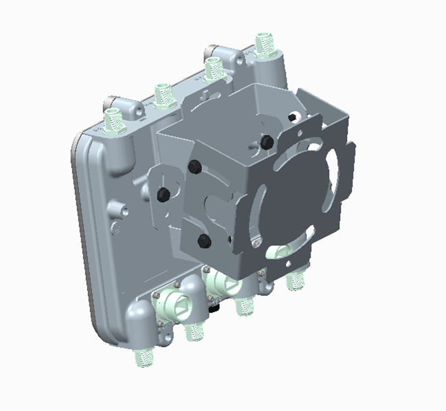
AP-8163 Mounting Hardware Wall Mount
With the Access Point positioned so the gore vent is facing down, insert the
two M6 hex flange screws in the bottom holes on the sides of the Access Point
bracket section into the open slot connections on the bottom of the angle
adapter bracket section. Rotate the Access Point bracket section upward and
align the top holes on the sides with the top holes on the angle adapter bracket
section. Insert two M6 hex flange screws into the top holes on the angle adapter
bracket section.
Use a torque wrench or a ratchet and a 10mm socket, or an adjustable wrench, to
finish attaching the angle adapter bracket section to the Access Point bracket
section with the four M6 hex flange screws in the open slot connections and the
top holes on the angle adapter bracket section. Do not tighten the screws until
all rotation and tilt adjustments are complete.
To adjust the position of the Access Point, rotate the Access Point bracket
section (plus or minus 15 degrees) and tilt the angle adapter bracket section
(up to 45 degrees).
Use a torque wrench or a ratchet and a 10mm socket, or an adjustable wrench, to
tighten all screws when all adjustments are complete.
Tighten all hex flange screws to 60 inch pounds (lbf-in).


 Print
this page
Print
this page Email this topic
 Feedback
 View PDF
 Download EPUB