Configuring the WAN(s)
As a third step, configure the two WANs linked to the B02 appliance: Internet and MPLS.
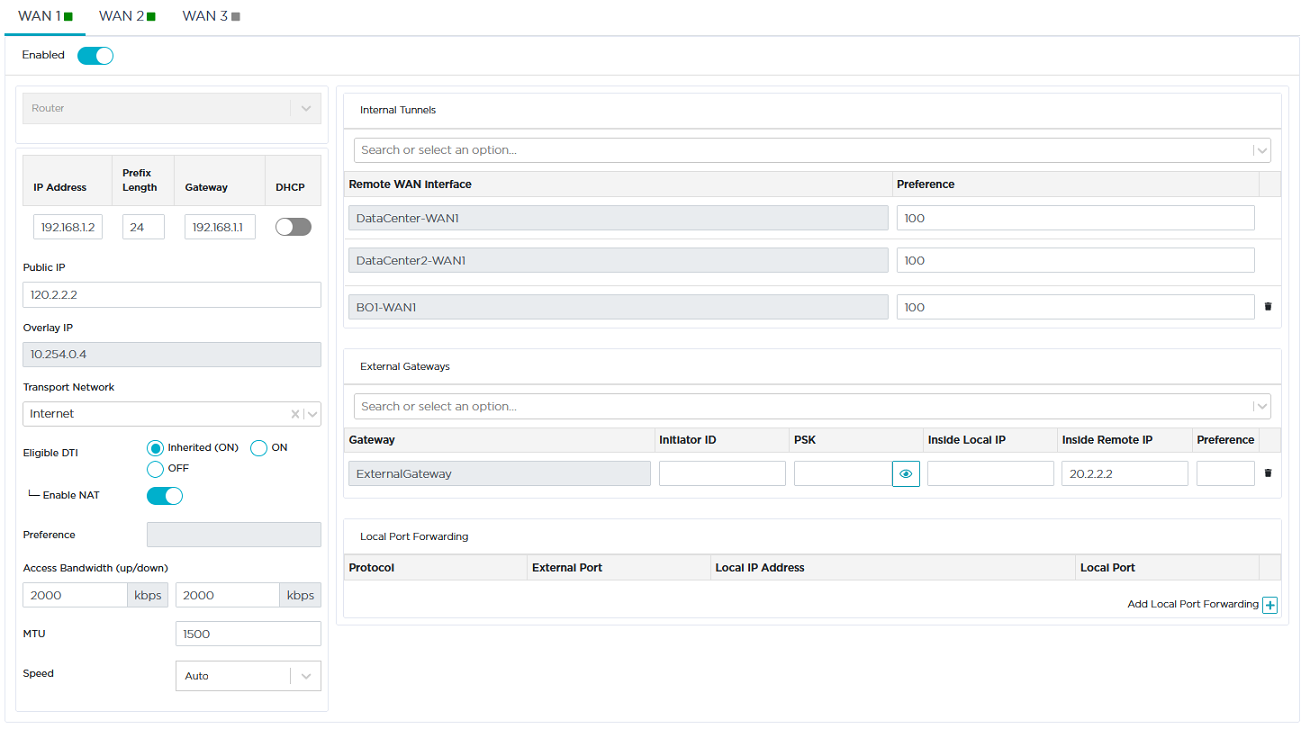
Refer to "Use Case 2" diagram where WAN1 (Internet) details are displayed in orange.
|
1
|
Activate the WAN through the  icon. You may now enter field data. icon. You may now enter field data. |
|
2
|
Select the Router option for this L3 interface. |
|
3
|
Do not activate the DHCP function to proceed with Step 4. |
|
4
|
Enter the WAN1 interface static information, 192.168.1.2 as IP Address, 24 as Prefix length. This address must be static to enable the configuration of Port Forwarding on the Internet Access router. |
|
5
|
Enter the Default Gateway: 192.168.1.1 |
|
6
|
Define the Public IP address (120.2.2.2) which corresponds to the WAN side of the Internet Access router to which the WAN1 interface is connected. The Port Forwarding configuration of the Internet Access router enables this device to send the UDP packets to the appliance WAN1 on ports 500 (IKEv2) and 4500 (IPsec NAT Traversal). The Internet Access router also modifies the Egress packets in order to replace its 120.2.2.2 public address with the 192.168.1.2 WAN1 static address as destination address. |
|
7
|
As you already defined the 'Internet' type of Transport Network for the Data Center and B01 WANs, select it from the stack. |
When configuring a WAN for the first time, type the name of the network you are connected to, 'Internet' in the current example. Clearly identify each name through customization. Once a Transport Network type has been defined, you can select it from the stack when configuring subsequent WANs.
|
8
|
This interface is automatically eligible to DTI (Inherited ON) because you globally activated this policy for the 'Internet' Transport Network (refer to Advanced Configuration -> Transport Network Settings). You may also manage DTI individually for this Internet L3 interface by checking the ON or OFF options. |
|
9
|
Directly derived from the activated Eligible DTI option, keep the Enable NAT mode activated. This is a source-NAT where the LAN Management IP address (11.1.2.2) is replaced with the 192.168.1.2 WAN1 IP address. This NAT only applies to the traffic sent over the Internet. The traffic to the Data Center and to other Sites is transferred through the IPsec tunnels. |
If you deactivate the Enable NAT mode which controls the firewall, incoming connections from the WAN are allowed to go to the LAN.
|
10
|
The Preference parameter is not available for a Spoke appliance. |
|
11
|
In the Access Bandwidth fields, define the up and down throughput (in kilobits per second) allocated to the WAN: 2000. |
|
12
|
Enter the MTU value which corresponds to the maximum number of bytes loaded in the Payload. The default value is 1500. |
|
13
|
Leave the Speed parameter to Auto to let the system define the speed of the interface, or you can force the speed to 100FD or 1000FD. The full duplex speed is expressed in megabits per second. |
|
14
|
The Internal Tunnels stack of values contains the WAN interfaces of the remote spoke sites which are connected to the same network. These interfaces are automatically detected by the Orchestrator. Since you connected the current appliance to the B01 appliance, the 'B01-WAN1' remote WAN interface is automatically specified in the list of interfaces and enables you to validate the tunnel between B02 and B01. See "Configuring the WAN" for the B01 appliance. |
Note: The Local Port Forwarding configuration panel is not used for this interface.
|
16
|
Validate your input by hitting the Create button. The Overlay IP address is generated by the system as soon as tunnels are created. |
If the appliance already exists and you modify any data, click the Update button.
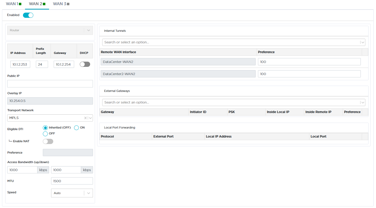
Refer to "Use Case 2" diagram where WAN2 (MPLS) details are displayed in green.
|
1
|
Activate the WAN through the icon. You may now enter field data. |
|
2
|
Select the Router option for this L3 interface. |
|
3
|
Enter the interface information, 10.1.2.253 as IP Address, 24 as Prefix length. |
|
4
|
Enter the Default Gateway: 10.1.2.254 |
|
5
|
Do not activate the DHCP function since the IP address of the WAN2 interface is static. |
|
6
|
As you already defined the 'MPLS' type of Transport Network for the Data Center WANs, select it from the stack. |
When configuring a WAN for the first time, type the name of the network you are connected to, 'MPLS' in the current example. Clearly identify each name through customization. Once a Transport Network type has been defined, you can select it from the stack when configuring subsequent WANs.
|
7
|
Leave the Eligible DTI parameter to 'Inherited (OFF)'. It corresponds to your configuration in Advanced Configuration -> Transport Network Settings where you did not activate eligibility to DTI for MPLS interfaces. |
|
8
|
Do not activate the Enable NAT mode since a private network is used (MPLS). |
|
9
|
The Preference parameter is not available for a Spoke appliance. |
|
10
|
In the Access Bandwidth fields, define the up and down throughput (in kilobits per second) allocated to the WAN: 1000. |
|
11
|
Enter the MTU value which corresponds to the maximum number of bytes loaded in the Payload. The default value is 1500. |
|
12
|
Leave the Speed parameter to Auto to let the system define the speed of the interface, or you can force the speed to 100FD or 1000FD. The full duplex speed is expressed in megabits per second. |
|
13
|
Validate your input by hitting the Create button. The Overlay IP address is generated by the system as soon as the tunnel is created. |
If the appliance already exists and you modify any data, click the Update button.
Also see how to configure:
Data Center appliance WANs
a multi-appliance Branch Office Site
traffic redirection to an external gateway
traffic redirection to a web security gateway
traffic redirection to a cloud gateway
traffic redirection to EdgeSentry
a multi-appliance Data Center