Refer to the image in this procedure for the back panel features.

Note
The unit comes with only one power supply. Users have the option to purchase an optional power supply and a cable. Using the optional power supply, the user can create a redundant power supply.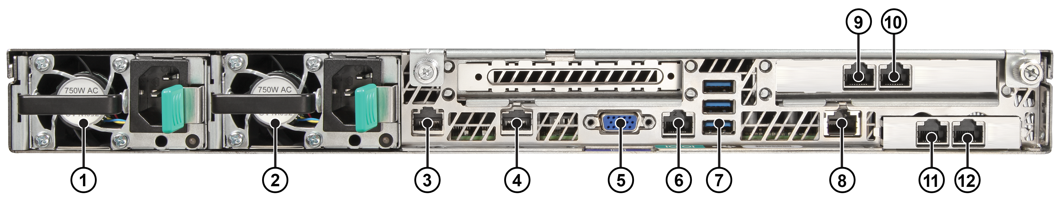
| Port Number | Description |
|---|---|
| 1 | Power Supply Module #1 |
| 2 | Power Supply Module #2 |
| 3 | Mgmt Port, 1 GbE RJ45 (eth0) |
| 4 | Port 4 (not used, plugged) |
| 5 | Video Connector |
| 6 | RJ45 Serial-A Port |
| 7 | USB 2.0/3.0 Ports |
| 8 | RMM4 NIC Port (not used, plugged) |
| 9 | Data Port 1, 1GbE RJ45(esa0) |
| 10 | Data Port 2, 1GbE RJ45(esa0) |
| 11 | Data Port 3, 1/10GbE SFP+(esa2) |
| 12 | Data Port 4, 1/10GbE SFP+(esa3) |
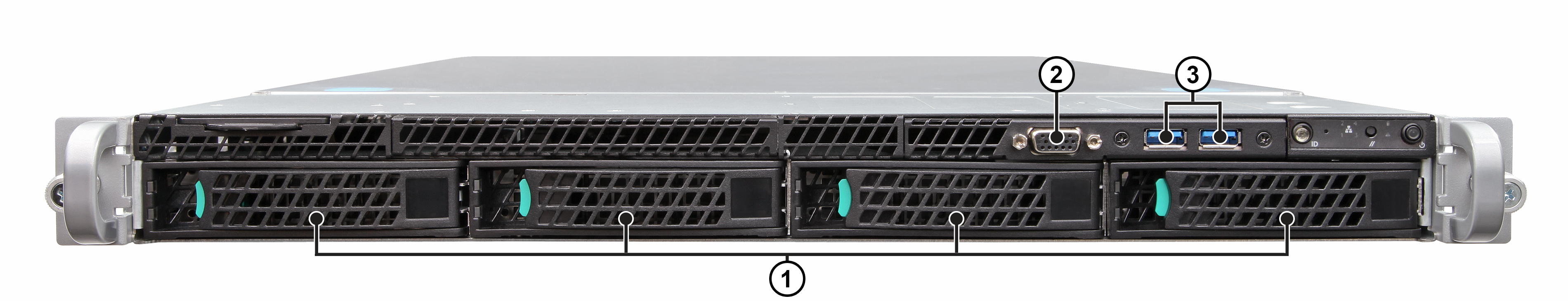
| Port Number | Description |
|---|---|
| 1 | Hard Disk Drive Bays (only the Hard Drive slot on the left is used) |
| 2 | Front Video Connector |
| 3 | USB 2.0/3.0 Ports |
Note
Although the appliance has five USB connectors (two on the front panel and three on the back panel), only one USB connector can be in use at any one time.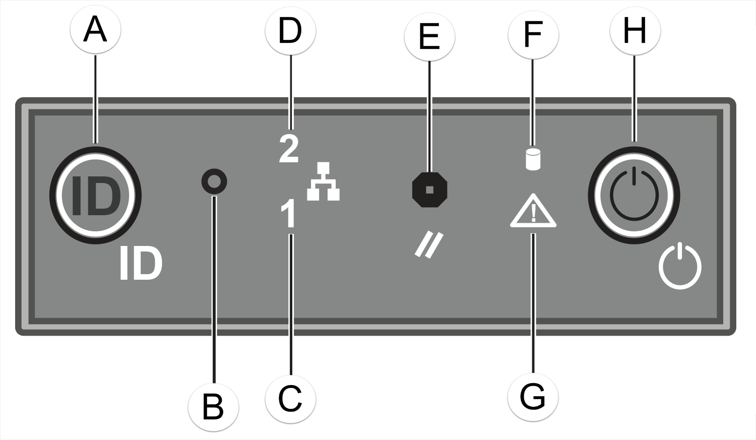
| Marking | Description |
|---|---|
| A | System ID Button w/ Integrated LED |
| B | NMI Button |
| C | Mgmt Port Activity LED |
| D | Not Used |
| E | System Cold Reset Button |
| F | Drive Activity LED |
| G | System Status LED |
| H | Power Button w/ Integrated LED |
 Print
this page
Print
this page Email this topic
 Feedback
 View PDF
 Download EPUB