The following example shows how to use full automation, partial automation, or
manual configuration to set up a redundant controlling bridge (CB) topology with
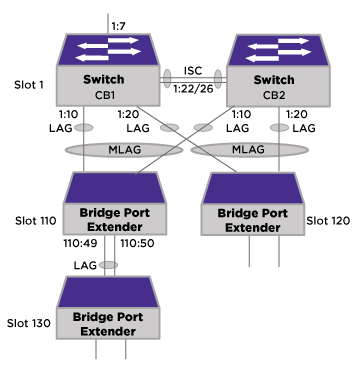
three attached bridge port extenders (BPEs) in a two-tier structure (see Redundant CBs with
Two-Tier BPEs Topology).
-
Connect the CBs.
-
Decide whether to use full or partial automation, or manual setup to configure
the Extended Edge
Switching topology:
-
Create the peer relationship
between the CBs on CB1:
enable sharing 1:22 group 1:22,1:26 lacp
create vlan isc tag 100
configure isc ipaddress 1.1.1.1/24
configure isc add port 1:22 tagged
create mlag peer vpex_peer
configure mlag peer vpex_peer ipaddress 1.1.1.2
-
Create the peer relationship
between the CBs on CB2:
enable sharing 1:22 group 1:22,1:26 lacp
create vlan isc tag 100
configure isc ipaddress 1.1.1.2/24
configure isc add port 1:22 tagged
create mlag peer vpex_peer
configure mlag peer vpex_peer ipaddress 1.1.1.1
-
Start MLAG orchestration on
CB1:
start orchestration mlag vpex_peer

Note
The CLI prompt changes to
inform you that you are in orchestration mode.
Using orchestration mode enforces that all configuration commands are now
checkpointed to the MLAG peer switch.
-
Create LAGs between CB and
first-tier BPEs by substituting the following commands in step 3:
Slot-1 VPEX X670G2-48x-4q.1 # enable sharing 1:10 group 1:10 lacp
Slot-1 VPEX X670G2-48x-4q.2 # enable sharing 1:20 group 1:20 lacp
-
Set up the rest of the MLAG by
executing the commands in the Manual Configuration Example, inserting the following commands between step 2 and
3:
enable mlag port 1:10 peer vpex_peer id 101
enable mlag port 1:20 peer vpex_peer id 102