A four-post rack-mounting kit (XN-4P-RKMT301 for SLX9740-80C or XN-4P-RKMT302 for
SLX9740-40C) is included in the box with your switch router. The kit contains an
instruction sheet, along with the following components:
Two slider assemblies
including inner rail (member) or intermediate rail (member), and outer rail
(member).
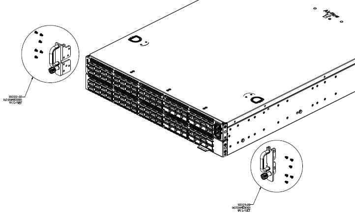
Two front mounting ears with
black thumb screws in the middle (for SLX9740-40C), or a black thumb screw
and handle (for SLX9740-80C). These pieces attach directly to both sides of
the device housing.
Mounting ears - Black rack
ears with a thumb screw in the middle (2 count).
Black mounting ear screws (6
count for front two rack ears of SLX9740-40C and 12 count for front two rack
ears of SLX9740-80C).
Grounding screws - M4 screws
to install the lug cables (not provided) to the rack on SLX9740-40c (4
count).
Rail screws - M4 screws to
secure the inner rail to the device (2 count).
To attach your device to a four-post rack, follow these steps:
On the sides of the device,
screw on the mounting ears. For SLX9740-80C, screw the mounting ears to the top
of the switch router, aligned with ports 1-40.
Mounting ears
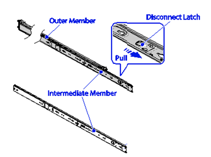
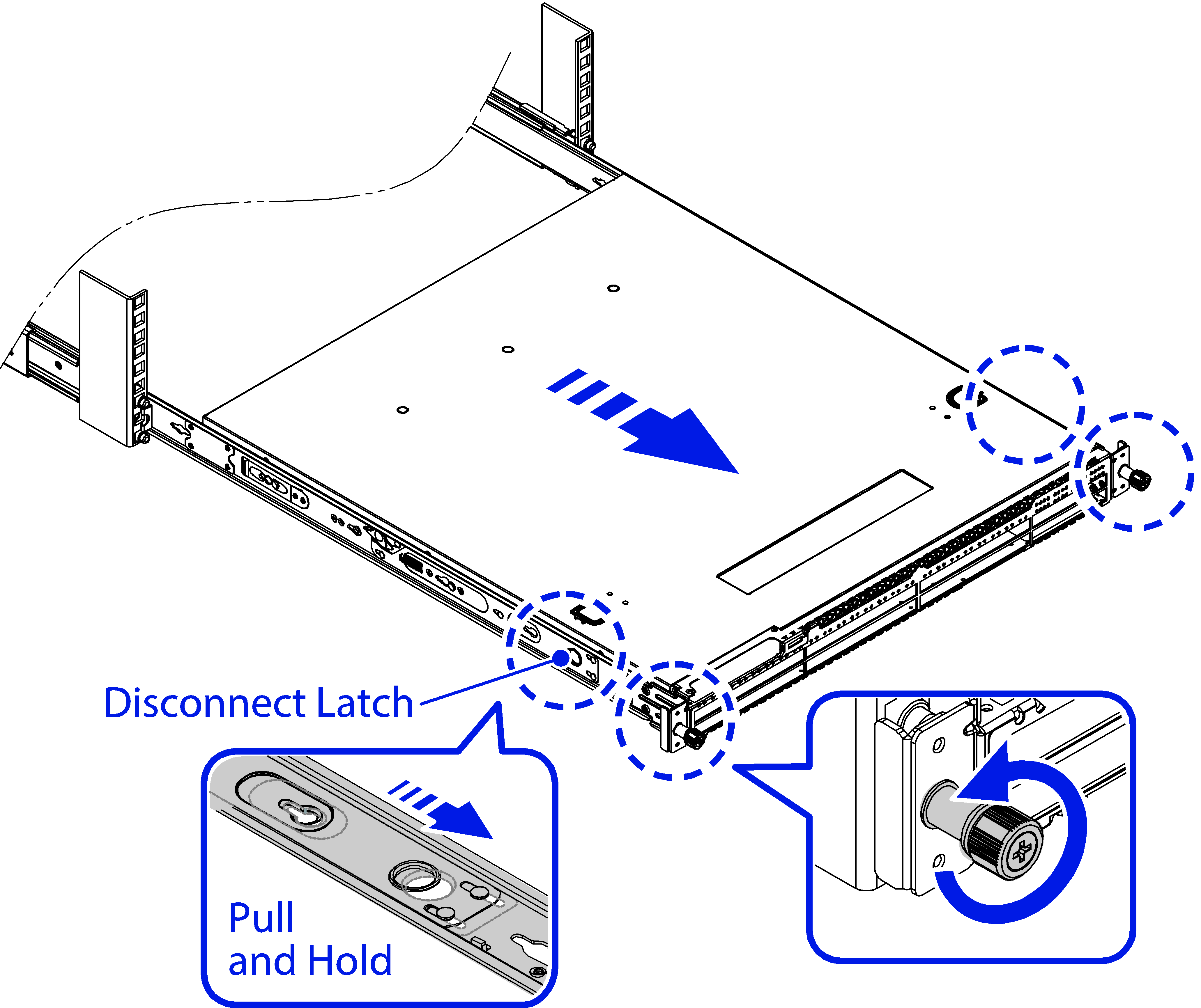
Pull the inner rail out until it is fully extended, then push the disconnect
latch forward to release the inner rail from the middle rail and remove the
inner rail.
Remove inner rail
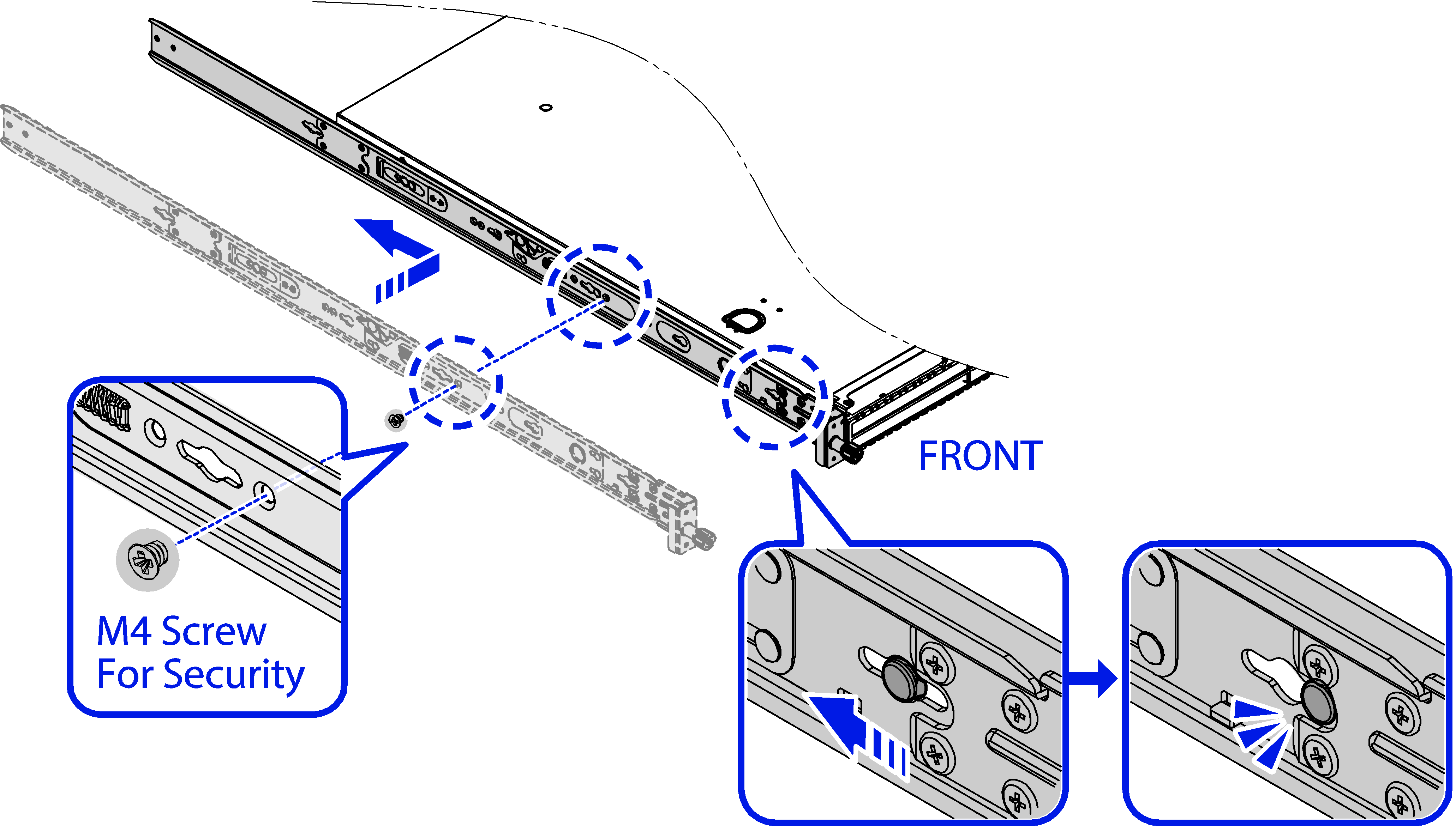
Align the hooks on the device
with the holes in the inner rail, and then slide the inner rail backward until
it is locked in place.
Secure the inner rail to the
device with one M4 rail screw per side. Repeat this step to install another
inner rail.
Outer rail
installation - front
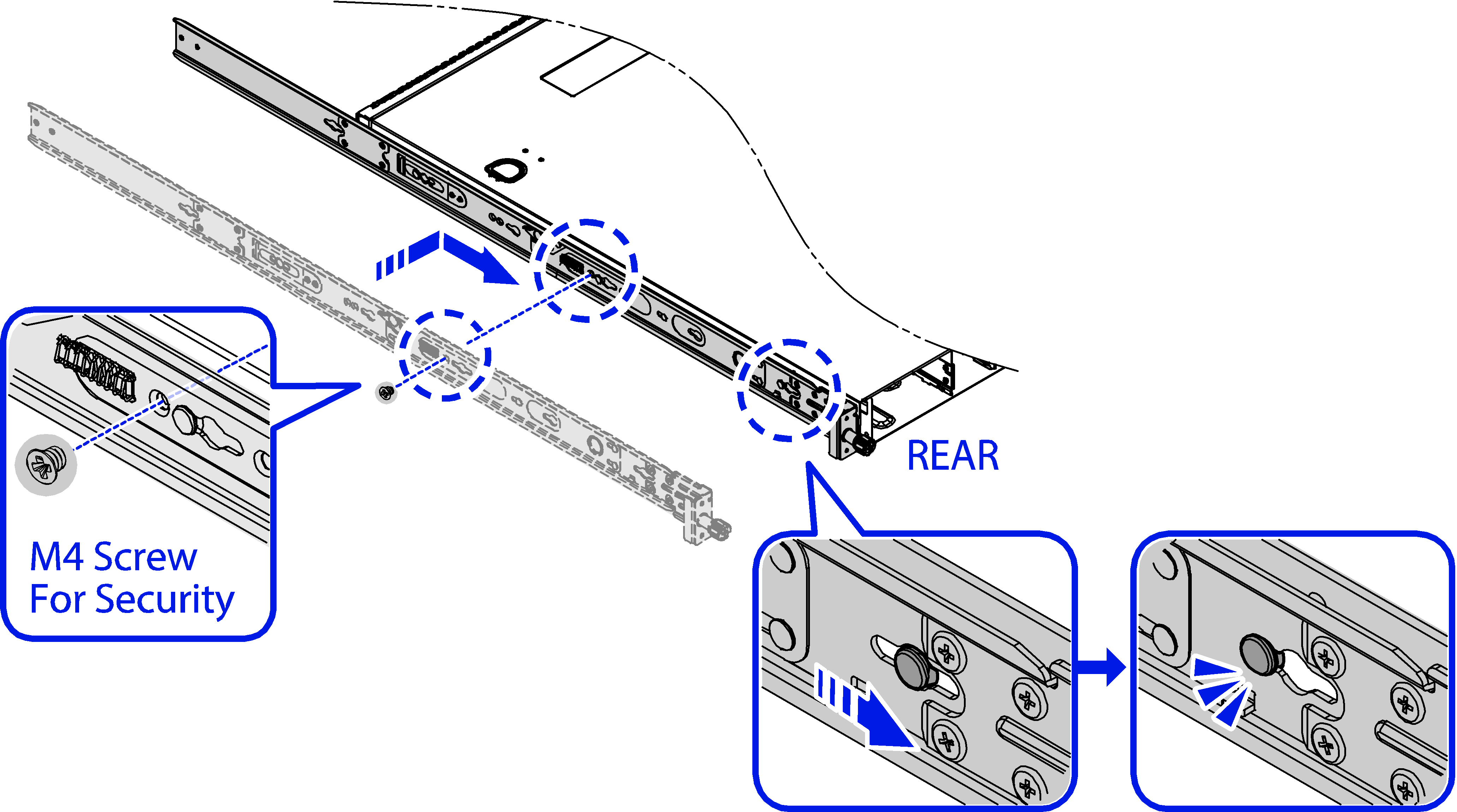
Outer rail
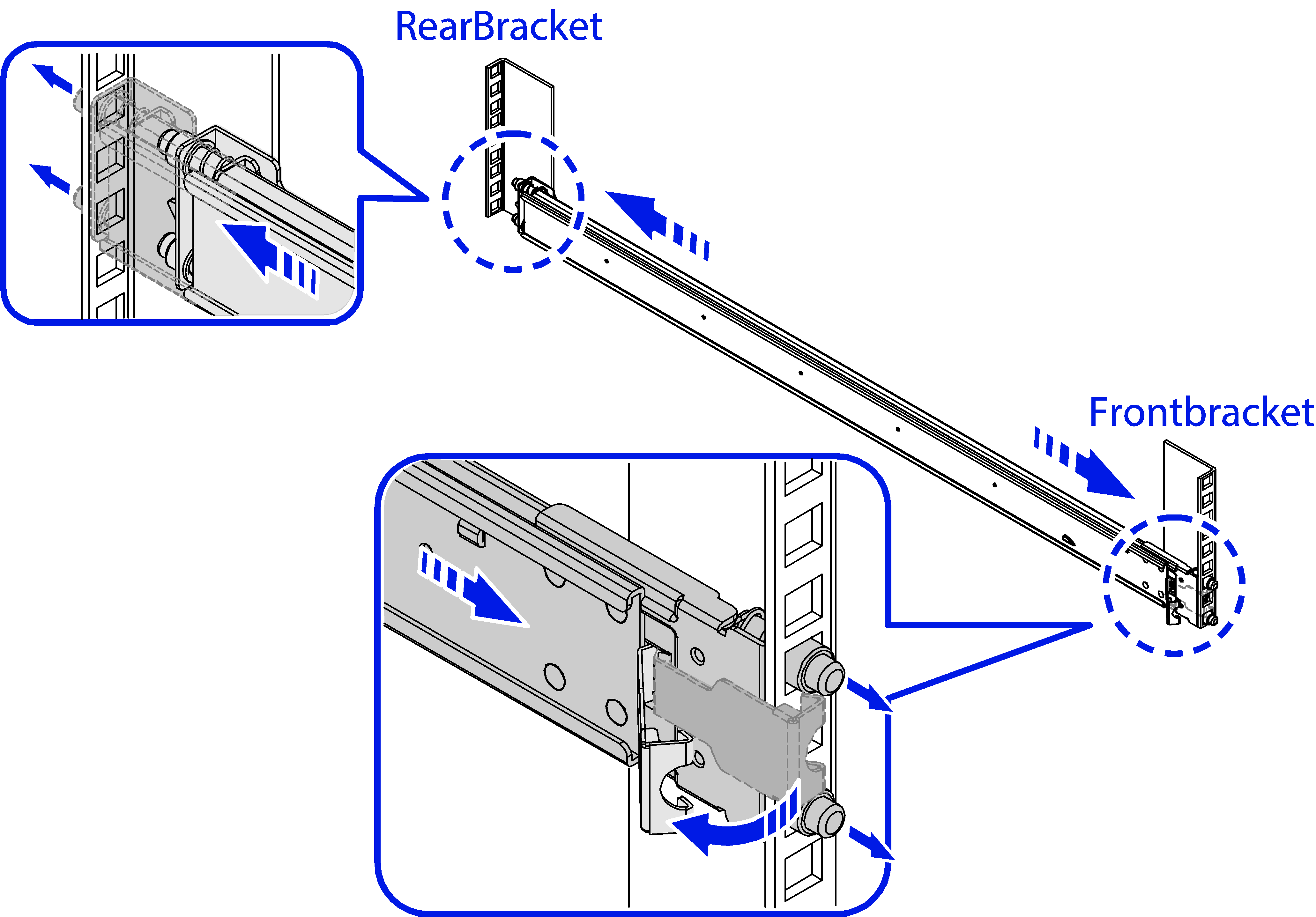
installation - rear
For the front brackets, pull the latch and install the outer rail by aligning
the hooks with the front rack holes. Then release the latch to lock the hooks
into place.
For the rear brackets, align and push the rail firmly into the rear rack until
it clicks into place. Make sure the L-shaped bracket is facing inward.
Install outer rail
Slide the inner rails on the
device into the middle rails and push the device all the way to the rear of the
rack.
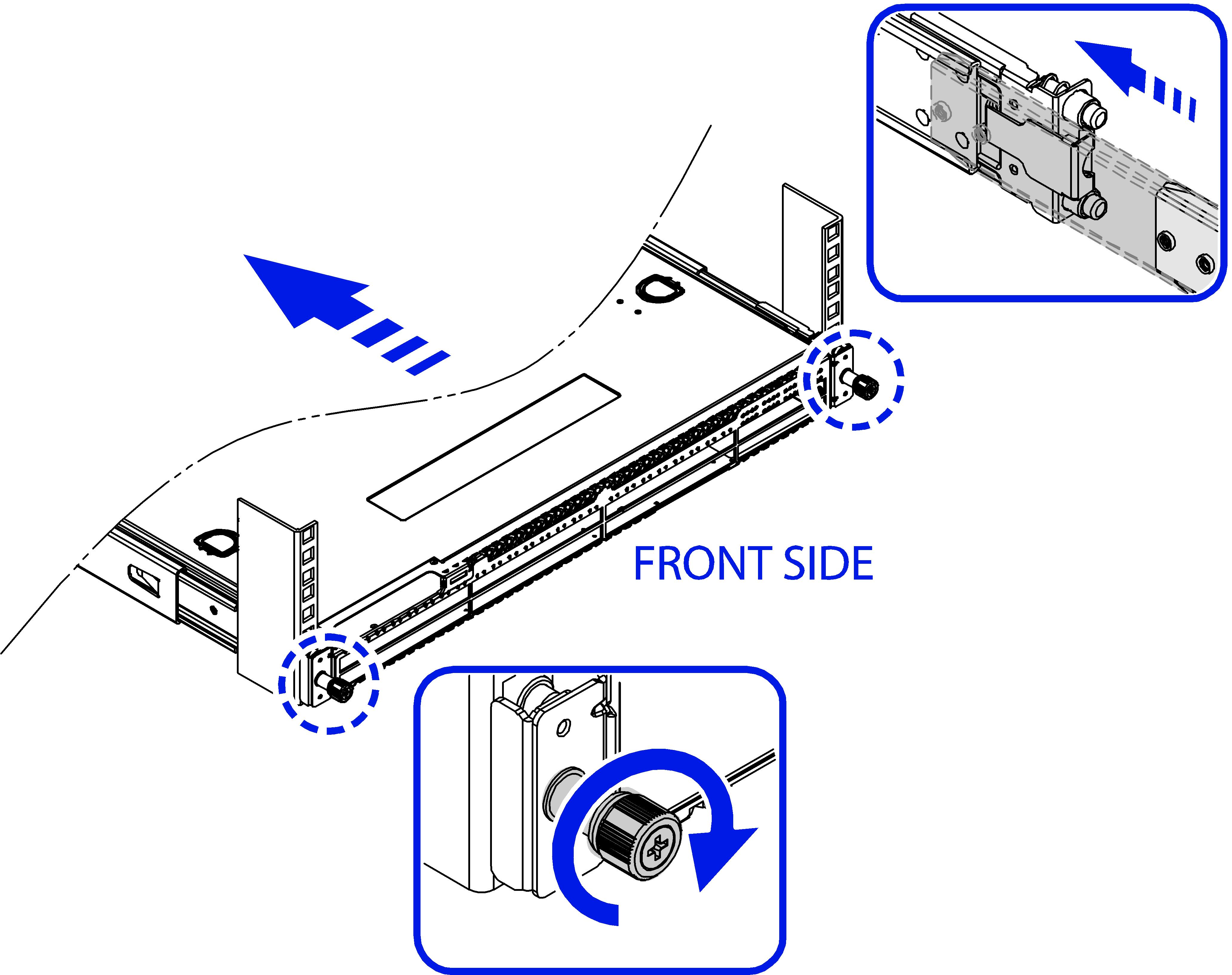
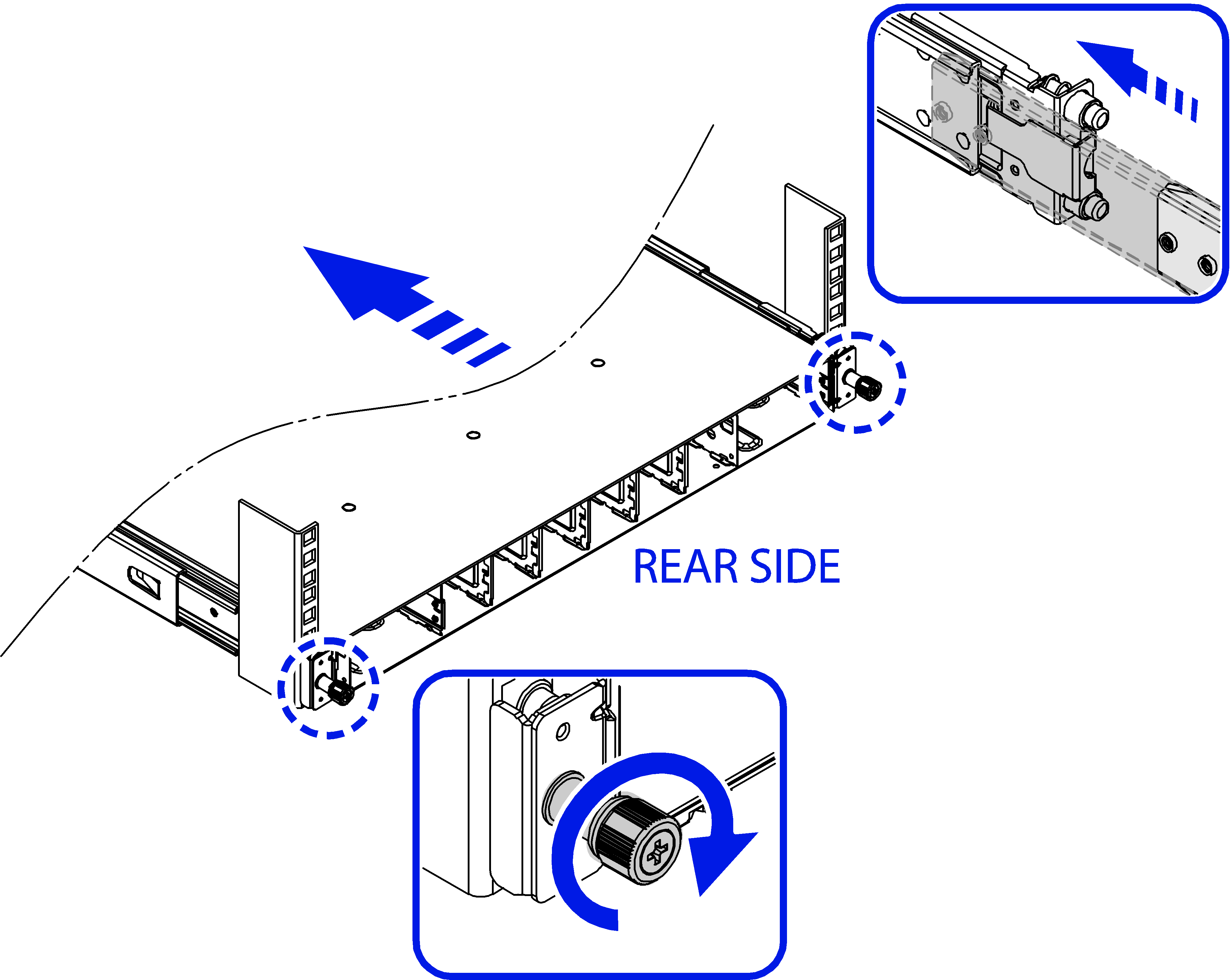
Securing rails -
front
Securing rails -
rear
Screw the mounting ear thumbscrews into the rack rails to hand tightness.
The completed assembly is shown in the Figure Completed Installation:
Switch Router in 4-Post Rack.
Completed
Installation: Switch Router in 4-Post Rack
Install the ground lug cables to
the rack using the four screws provided.
4-post grounding location
Verify that the device is
leveled and is firmly attached to the rack.
Push the disconnect latch to
release the device when removing the device after it is fully extended.