Multi-Backup VRRP Configuration Example shows a multi-backup sample configuration.
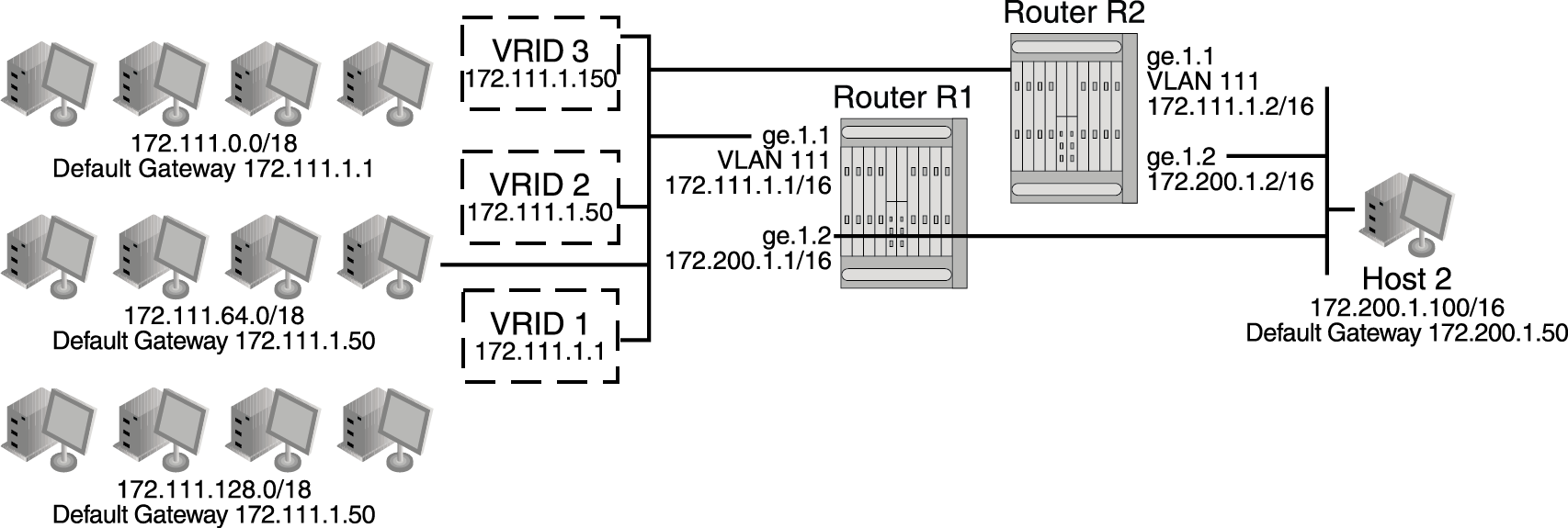
Three VRRP instances are configured on VLAN 111 for both devices on Router R1‘s interface, 172.111.1.1, and Router R2‘s interface, 172.111.1.2. Each virtual router is given a different virtual IP address that is used as a default gateway by a subset of hosts that reside of the LAN segment. Because interfaces on Router R1 and Router R2 for VLAN 111 are configured as belonging to VRID 1, 2, and 3, VRRP will support resiliency between these interfaces if one interface becomes in-operational.
To load balance traffic generated from the hosts on the 172.111.0.0/16 network, the hosts are partitioned into being configured with default gateways matching the virtual IP address of the VRRP virtual routers, and the VRRP Master for each VRRP instance is configured for distribution across Router R1 and Router R2. It is known that Router R1‘s interface, 172.111.1.1, will become Master for VRID 1 because it is the IP address owner for the virtual router. This interface is also configured to be Master for VRID 3 by raising its VRRP priority in VRRP instance 3 to 200. Therefore, Router R1‘s interface 172.111.1.1 will be Master for VRID 1 and VRID 3 handling traffic on this LAN segment sourced from subnets 172.111.0.0/18 and 172.111.128.0/18. Router R2‘s interface is configured to be the Master for VRID 2 by raising its VRRP priority in VRRP instance 2. Therefore, Router R2‘s interface 172.111.1.2 will be Master for VRID 2 handling traffic on this LAN segment sourced from subnets 172.111.64.0/18.
In this configuration, an interface on VLAN 111 for Router R1 or Router R2, or VRID 1, 2, or 3 fails, the interface on the other router will take over for forwarding outside the local LAN segment.
System(rw)->configure
System(rw-config)->interface vlan 111
System(rw-config-intf-vlan.0.111)->vrrp create 1 v2-IPv4
System(rw-config-intf-vlan.0.111)->vrrp address 1 172.111.1.1
System(rw-config-intf-vlan.0.111)->vrrp enable 1
System(rw-config-intf-vlan.0.111)->vrrp create 2 v2-IPv4
System(rw-config-intf-vlan.0.111)->vrrp address 2 172.111.1.50
System(rw-config-intf-vlan.0.111)->vrrp enable 2
System(rw-config-intf-vlan.0.111)->vrrp create 3 v2-IPv4
System(rw-config-intf-vlan.0.111)->vrrp address 3 172.111.1.150
System(rw-config-intf-vlan.0.111)->vrrp priority 3 200
System(rw-config-intf-vlan.0.111)->vrrp enable 3
System(rw-config-intf-vlan.0.111)->no shutdown
System(rw-config-intf-vlan.0.111)->exit
System(rw-config)->
System(rw)->configure
System(rw-config)->interface vlan 111
System(rw-config-intf-vlan.0.111)->vrrp create 1 v2-IPv4
System(rw-config-intf-vlan.0.111)->vrrp address 1 172.111.1.1
System(rw-config-intf-vlan.0.111)->vrrp enable 1
System(rw-config-intf-vlan.0.111)->vrrp create 2 v2-IPv4
System(rw-config-intf-vlan.0.111)->vrrp address 2 172.111.1.50
System(rw-config-intf-vlan.0.111)->vrrp priority 2 200
System(rw-config-intf-vlan.0.111)->vrrp enable 2
System(rw-config-intf-vlan.0.111)->vrrp create 3 v2-IPv4
System(rw-config-intf-vlan.0.111)->vrrp address 3 172.111.1.150
System(rw-config-intf-vlan.0.111)->vrrp enable 3
System(rw-config-intf-vlan.0.111)->no shutdown
System(rw-config-intf-vlan.0.111)->exit
System(rw-config)->
 Print
this page
Print
this page Email this topic
 Feedback
 View PDF
 Download EPUB