Virtual Private Port Services permit the user to extend a virtual wire through an arbitrary routed network using GRE with transparent bridging. This feature is referred to as a Virtual Private Port Service (VPPS). The configuration on each end of the tunnel specifies a physical port to be connected to the VPPS. Once configured in this manner, any packets arriving on that physical port are immediately encapsulated and routed to the other end of the tunnel. When the packet arrives at the remote end of the tunnel, it is immediately de-encapsulated and sent out the configured port on that end of the tunnel. The net effect is to create a direct connection between each end of the tunnel. No switch or router configuration affects the original packet. The packet arriving at the ingress port is tunneled without change to the tunnel‘s remote end.
Virtual Private Port Service Configuration Example presents a Virtual Private Port Service configuration example. In this example, a packet is sourced at PC1 (callout 1) and enters the VPPS at port ge.1.1 of Router 1 (callout 2). The VPPS is configured using a GRE L2 tunnel mode configuration on the L3 tunnel between Router 1 and Router 2. In our example the L3 tunnel configuration is limited to the configuration of a source and destination address. Tunnel Configuration Example for a more detailed L3 tunnel configuration example and walkthrough.
From the perspective of Router 1, the VPPS is configured with a L3 tunnel source of loopback address 88.88.88.1 (callout 3) and a L3 tunnel destination of loopback address 99.99.99.1 (callout 4). The VPPS ingress port is configured as Router 1‘s port ge.1.1. The VPPS egress port is Router 2‘s port ge.1.2 (callout 5) and is specified when configuring the GRE L2 tunnel mode on Router 2
From the perspective of Router 2, the VPPS is configured with a L3 tunnel source of loopback address 99.99.99.1 and a L3 tunnel destination of loopback address 88.88.88.1. The VPPS ingress port is configured as Router 2‘s port ge.1.2.
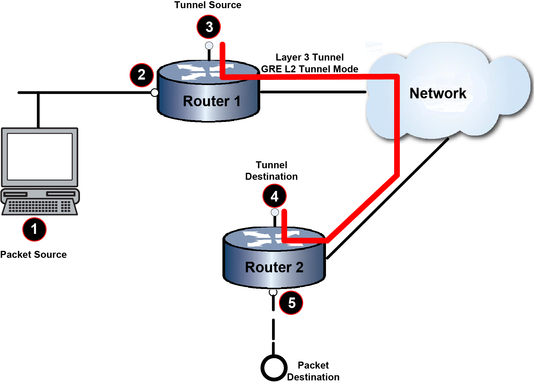
| 1 | PC 1, Packet Source, IP address 2111::2 | 4 | L3 Tunnel Destination Loopback Address 99.99.99.1 |
| 2 | Virtual Private Port Service Ingress Port ge.1.1 | 5 | Virtual Private Port Service Egress Port ge.1.2 |
| 3 | L3 Tunnel Source Loopback Address 88.88.88.1 |
This example shows how to set:
System(rw)->configure
System(rw-config)->interface tunnel 1
System(rw-config-intf-tun.0.1)->tunnel source 88.88.88.1
System(rw-config-intf-tun.0.1)->tunnel destination 99.99.99.1
System(rw-config-intf-tun.0.1)->tunnel mode gre l2 ge.1.1
System(rw-config-intf-tun.0.1)->no shutdown
System(rw-config-intf-tun.0.1)->
This example shows how to set:
System(rw)->configure
System(rw-config)->interface tunnel 1
System(rw-config-intf-tun.0.1)->tunnel source 99.99.99.1
System(rw-config-intf-tun.0.1)->tunnel destination 88.88.88.1
System(rw-config-intf-tun.0.1)->tunnel mode gre l2 ge.1.2
System(rw-config-intf-tun.0.1)->no shutdown
System(rw-config-intf-tun.0.1)->
 Print
this page
Print
this page Email this topic
 Feedback
 View PDF
 Download EPUB