The default method for flooding the broadcast/unicast/multicast (BUM) traffic from VXLAN overlay to remote VTEPs is through head-end replication over VXLAN underlay. This means the originating VTEP sends a separate copy to each of the destination VTEPs over VXLAN unicast tunnel to each VTEP.

On receiving overlay BUM traffic, VTEP 100.100.100.1 VXLAN encapsulates and sends two copies – one copy is destined to VTEP 101.101.101.1 and the other to 102.102.102.1.

Note
RED VNI does not span to VTEP 103.103.103.1.A multicast group address is assigned to a virtual network VNI. Each VTEP must use the same multicast group address for a given VNI. This must be administratively ensured.
When a VTEP discovers a remote VTEP, it learns the VNIs supported by the remote VTEP. The discovering VTEP triggers PIM (S, G) joins to the remote VTEP, for the multicast groups corresponding to the supported VNIs. As a result, a multicast distribution tree (MDT) is formed for each multicast group or each VNI.
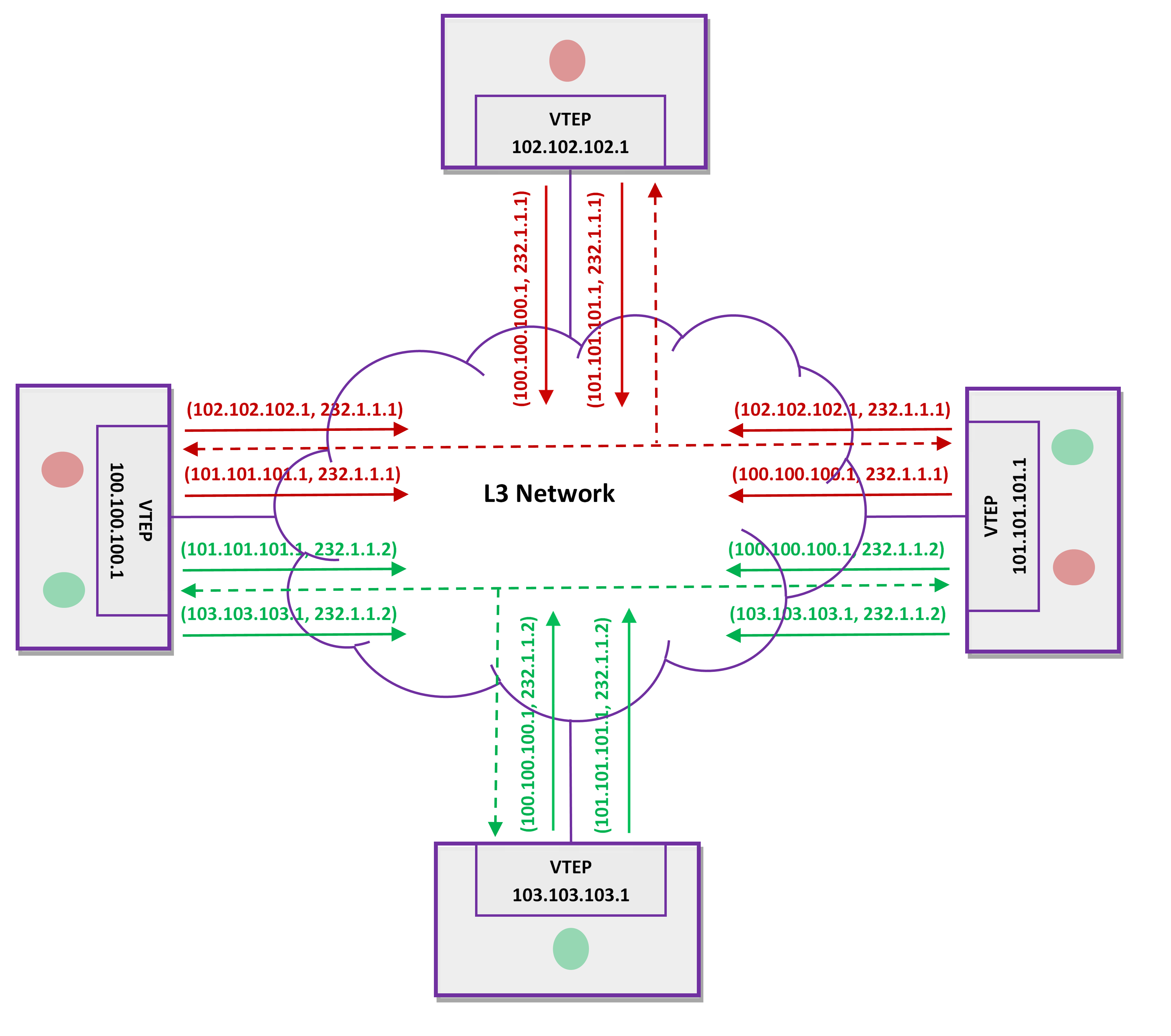
The RED VNI is assigned with 232.1.1.1 and GREEN VNI is assigned with 232.1.1.2. Observe the PIM joins triggered by each VTEP. The MDT for RED VNI is RED dash-tree (232.1.1.1) and the MDT for GREEN VNI is GREEN dash-tree (232.1.1.2).
The overlay BUM traffic is VXLAN encapsulated with multicast group IP (corresponding to the VNI) as the outer destination IP and sent over the MDT. At the very best scenario, the originating VTEP sends only one copy out. The replication is done en route hop-by-hop by the routers in the multicast tree present in L3 network. The routers in the L3 network must support PIM-SSM but need not be VXLAN aware.
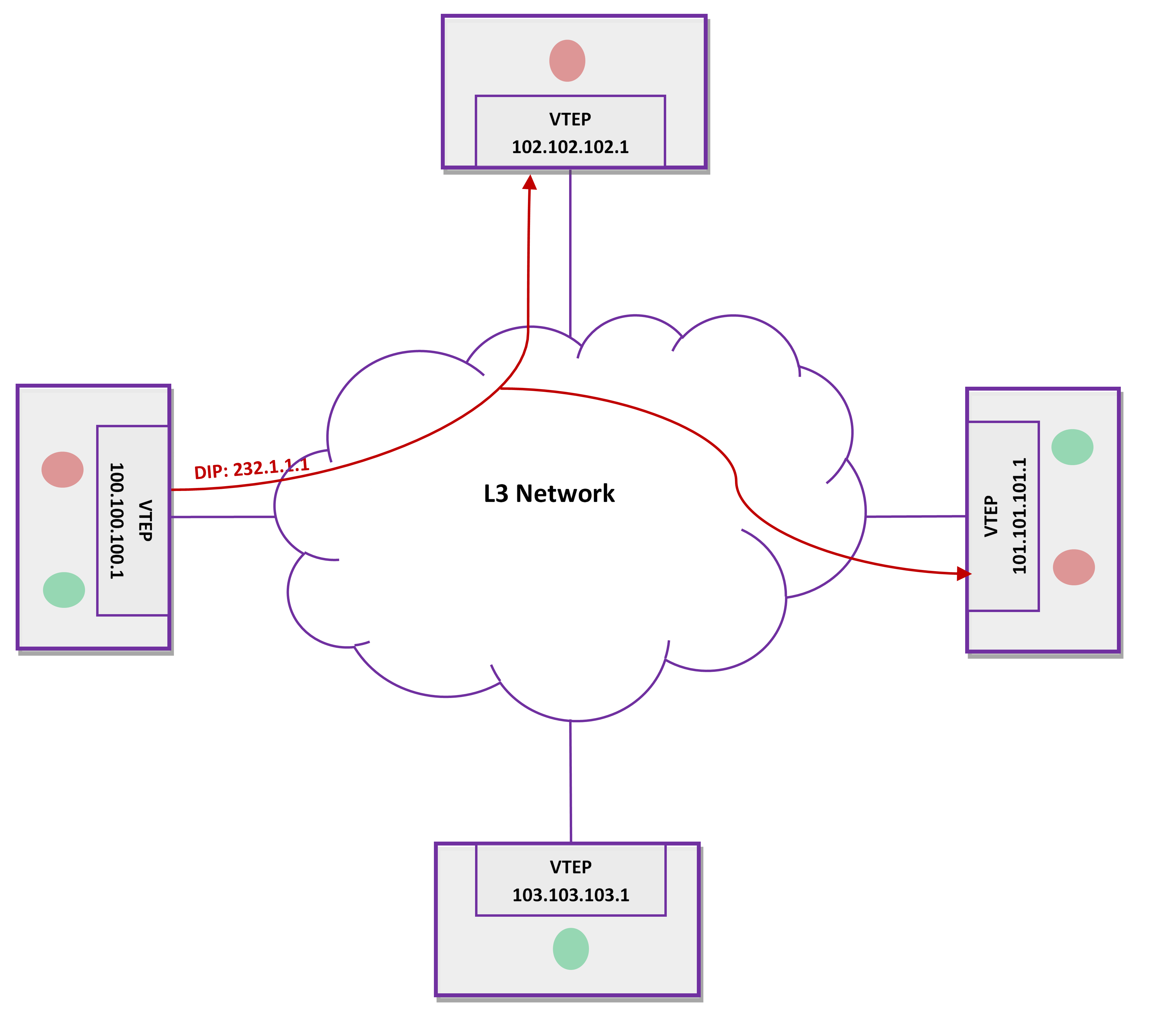
The following figure illustrates how VTEP 100.100.100.1 VXLAN encapsulates the traffic with destination IP as 232.1.1.1 and sends one copy out. The traffic flows across the L3 network over the MDT and reaches 101.101.101.1 and 102.102.102.1:
It is possible to automatically assign multicast group address for each VNI. The group address is picked from a user configured address range. The address is derived as depicted in the below figure. The group prefix is obtained by AND‘ing group address and mask. The group suffix bits come from the VXLAN network identifier (VNID).
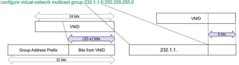
Using the command featured in the previous figure, it is possible to choose different variants of MDT as shown here:
configure virtual-network multicast group 232.0.0.0 255.0.0.0
configure virtual-network multicast group 232.1.1.1 255.255.255.255
configure virtual-network multicast group 232.1.1.0 255.255.255.252
| Virtual Network VNIs | Shared MDT |
| 1, 5, 9, 13, 17, and so on | 232.1.1.1 |
| 2, 6, 10, 14, 18, and so on | 232.1.1.2 |
| 3, 7, 11, 15, 19, and so on | 232.1.1.3 |
| 4, 8, 12, 16, 20, and so on | 232.1.1.0 |
In any of the previous options, a single VNI cannot use more than one multicast group address.
ExtremeSwitching X670-G2, X870, X690, X590, X695, X465 series switches.
Note
This feature should not be used with Assisted Replication.