The professional installer configures Radio RF ports where antenna
ports will be connected.
To configure radio RF ports through the Assistant:
Procedure
Log into the Wireless Assistant.
From the top menu, select
AP.
The Wireless AP screen
is displayed.
Select APs in the left
pane, then in the Wireless AP list, select the Wireless AP for which you want to
modify the properties.
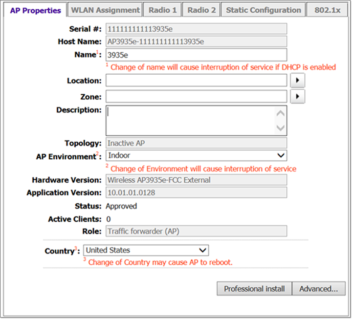
The AP Properties tab
displays Wireless AP information.
AP Properties for the
AP3935e
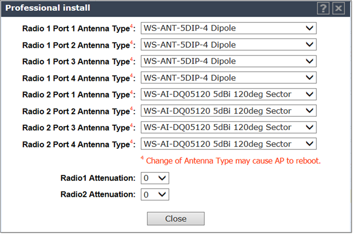
When configuring the AP3935e,
select Professional Install.
The Professional
Install dialog displays to configure the external antennas.
Professional Install
Dialog for the AP3935e
Modify the Radio Antenna Type as follows:
If attaching quad port antennas, configure all four RF ports with the
same antenna type.
If attaching triple port antennas, configure ports
1, 2, and 3 with the same antenna type and configure port 4 (non‐active
port) to No Antenna.
If attaching dual port antennas, configure ports 1
and 2 with the same antenna type and configure ports 3 and 4 (non‐active
ports) to No Antenna.
If attaching single port antennas, configure port
1to the selected antenna type and configure ports 2‐4 (non‐active ports)
to No Antenna.
Modify Radio Attenuation as follows:
Add any attenuation (dBm non‐negative) due to cable loss or attenuator
added to the line between AP port and the antenna.
Same attenuator loss is assumed and is required for all 4 ports of the
radio except when one or more ports is not connected to the antenna and
is properly terminated as describe in next step.
The professional installer is responsible for accurately configuring
port Attenuation. Never configure port attenuation higher than the
actual attenuation between the AP port and the antenna.
Install a terminator (rf 50 Ohm) on all ports where an antenna is not
connected.