Mounting the SSA Chassis on a Wall

After preparing the wall, follow these steps to mount the SSA chassis:

  1. Using four customer-supplied screws and wall anchors, secure the mounting bracket to the wall. See Securing the Wall Mounting Bracket to a Wall.

    The screws and wall anchors that you provide must be capable of supporting at least four times the combined weight of the SSA chassis and two power supplies.

    You must secure the mounting bracket to the wall in the orientation shown in Securing the Wall Mounting Bracket to a Wall.

    Click to expand in new window
    Securing the Wall Mounting Bracket to a Wall
    ../S-180/Graphics/ssa_ins_to_wall_horiz.png
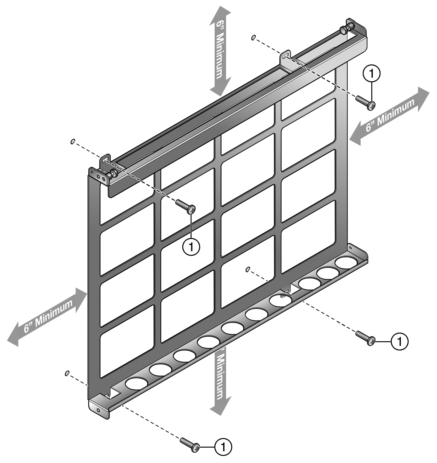
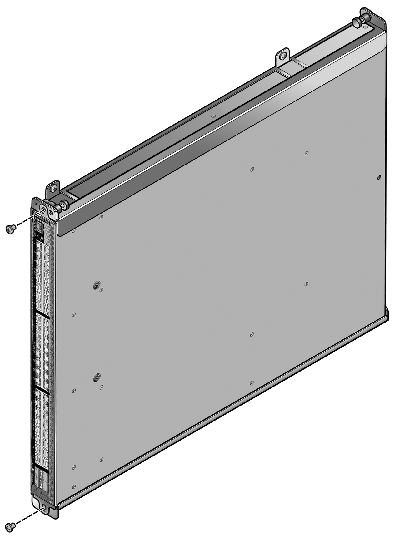
    1 = Customer-supplied screws
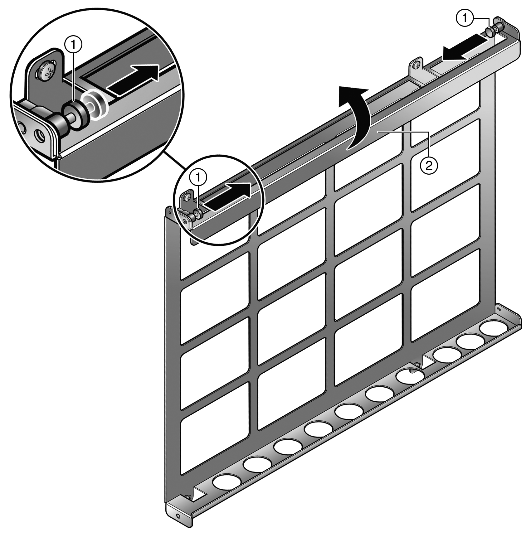
  2. Open the gate on the top side of the mounting bracket as shown in Opening the Gate.
    1. Pull the right and left plungers simultaneously to unlock the gate.
      To lock the plungers in the open position, rotate the opened plungers counter-clockwise.
    2. Swing the gate into the open position.
    Click to expand in new window
    Opening the Gate
    ../S-180/Graphics/ssa_open_gate.png
    1 = Right and left plungers 2 = Gate

    Mounting Bracket Gate in the Open Position shows the gate in the open position.

    Click to expand in new window
    Mounting Bracket Gate in the Open Position
    ../S-180/Graphics/ssa_gate_open_pos_horiz.png
  3. Holding the SSA with the I/O connectors facing left, slide the bottom side of the SSA chassis under the lip on the bottom side of the mounting bracket.
    See Installing the SSA in the Mounting Bracket.
    Note

    Note

    You must install the SSA chassis in the orientation shown in Installing the SSA in the Mounting Bracket: I/O connectors facing left, top of the SSA facing out. No other orientation of the SSA chassis is supported.
    Click to expand in new window
    Installing the SSA in the Mounting Bracket
    ../S-180/Graphics/ssa_ins_to_gate_horiz.png
  4. Insert the top side of the SSA chassis in the mounting bracket.
  5. Close the gate to hold the SSA chassis in place.
    See Closing the Gate.

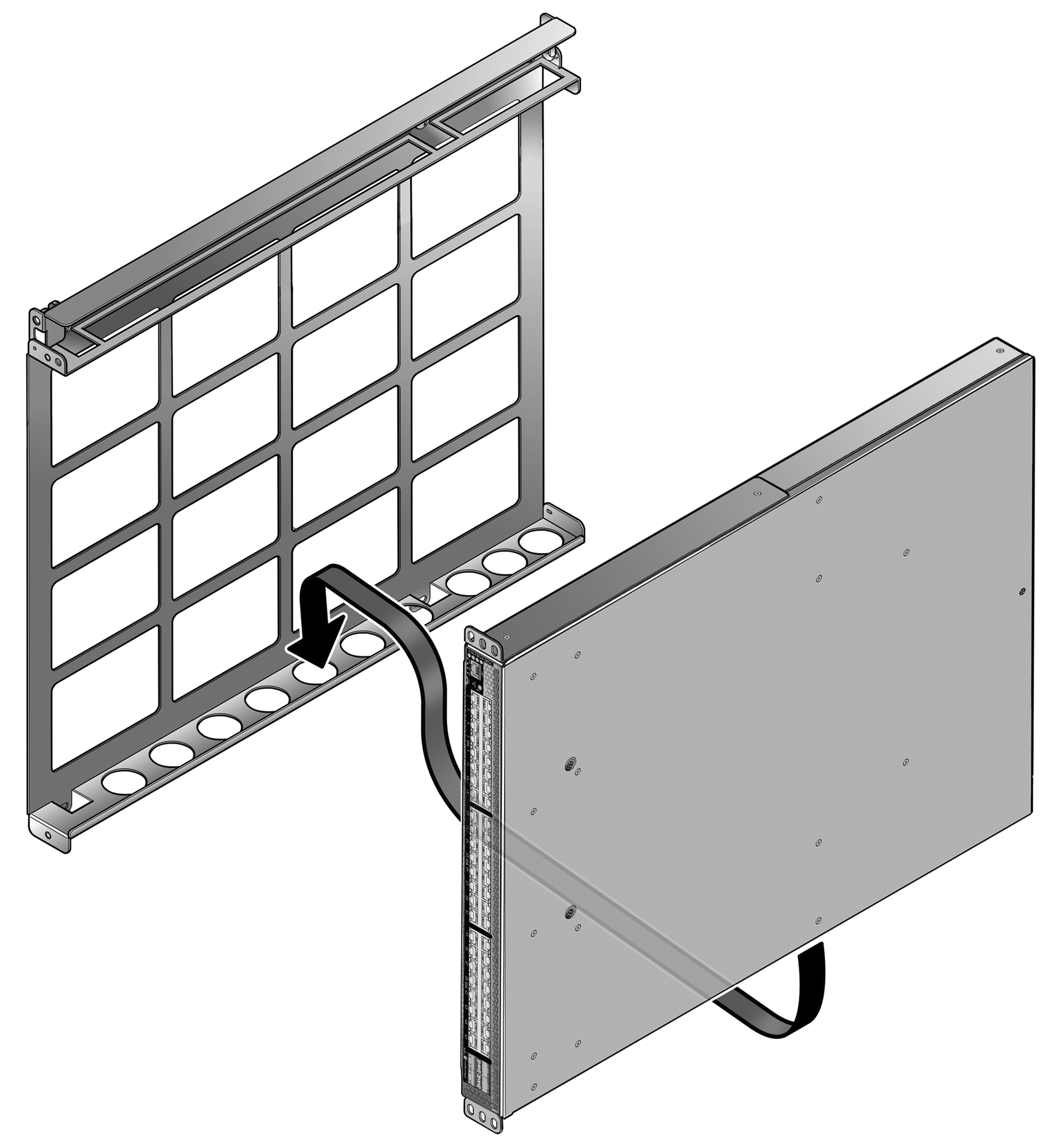
    Ensure that the plungers lock into place when you close the gate. If the plungers are in the open locked position, rotate the plungers clockwise until they unlock.
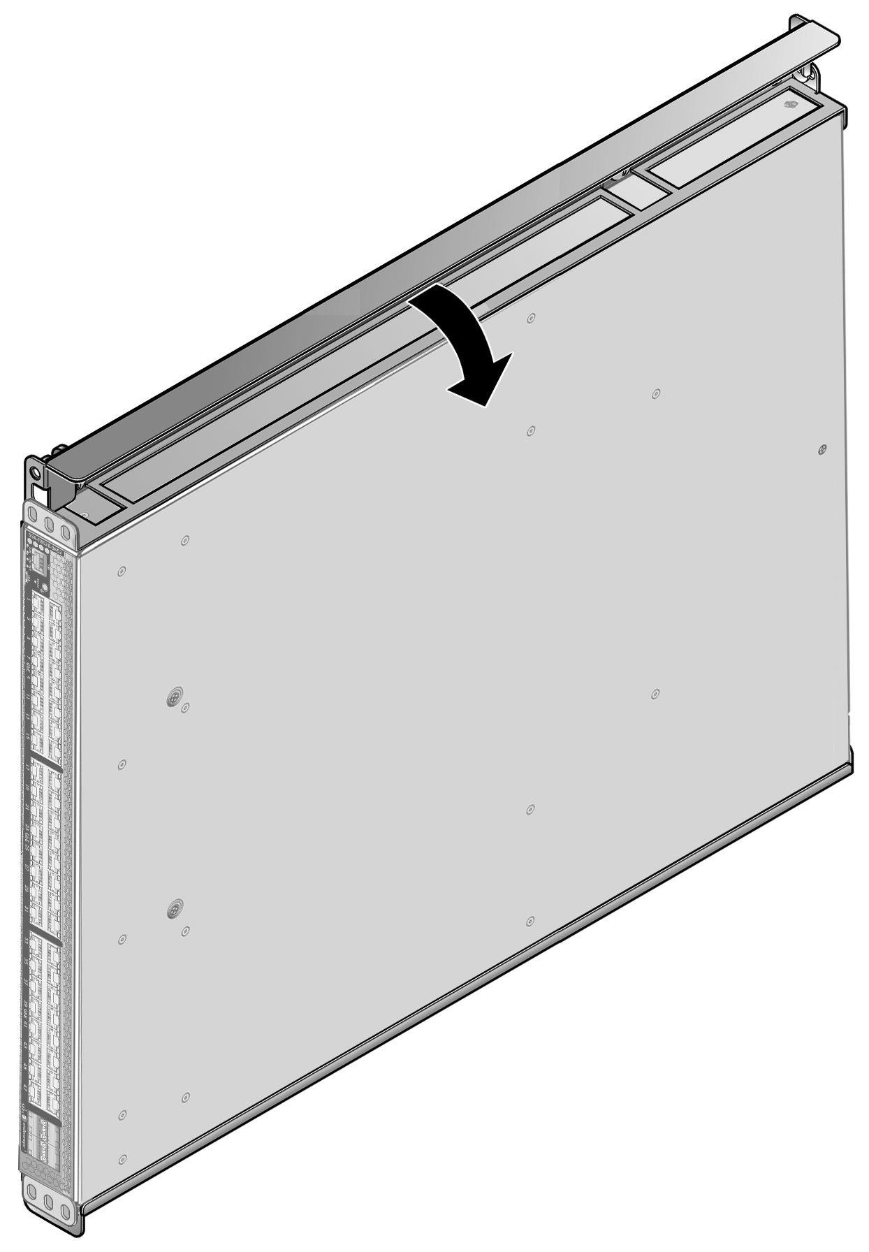
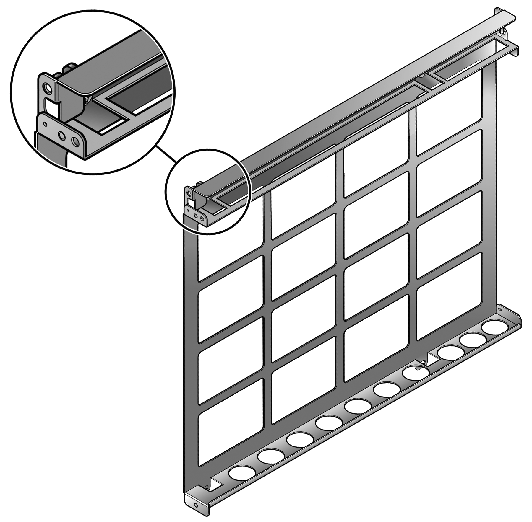
    Click to expand in new window
    Closing the Gate
    ../S-180/Graphics/ssa_close_gate_horiz.png
    1 = Gate
  6. Using the 10-32 screws included with the mounting bracket, secure the front of the SSA chassis to the left of the mounting bracket.
    See Securing the SSA Chassis to the Mounting Bracket.
    Click to expand in new window
    Securing the SSA Chassis to the Mounting Bracket
    ../S-180/Graphics/ssa_sec_to_brkt_2.png
You can now cable the I/O ports and power up the SSA chassis as described in Installation.