Replacing Fans F11-F13
To replace an F11-F13 fan,
follow these steps:
-
Put on the ESD wrist strap and attach it to the ground receptacle on the front of the SSA.
-
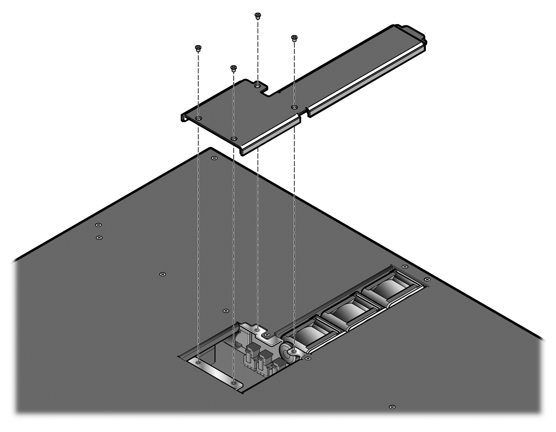
Remove the rear panel of the
SSA by unscrewing the four zinc (silver) screws from the rear panel.
-
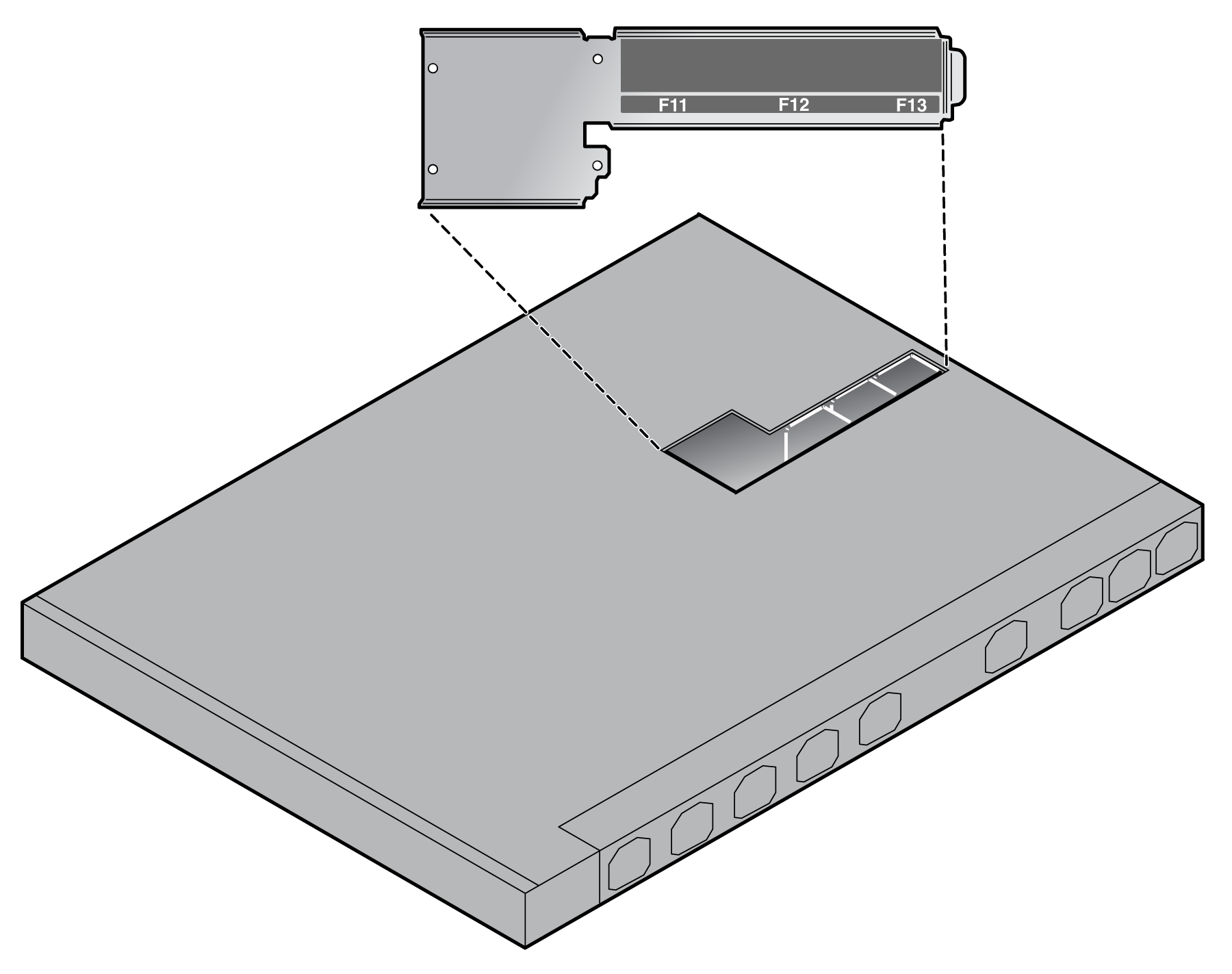
Set the side panel upside
down to view the label on the inside of the rear panel that indicates the position of
each fan.
-
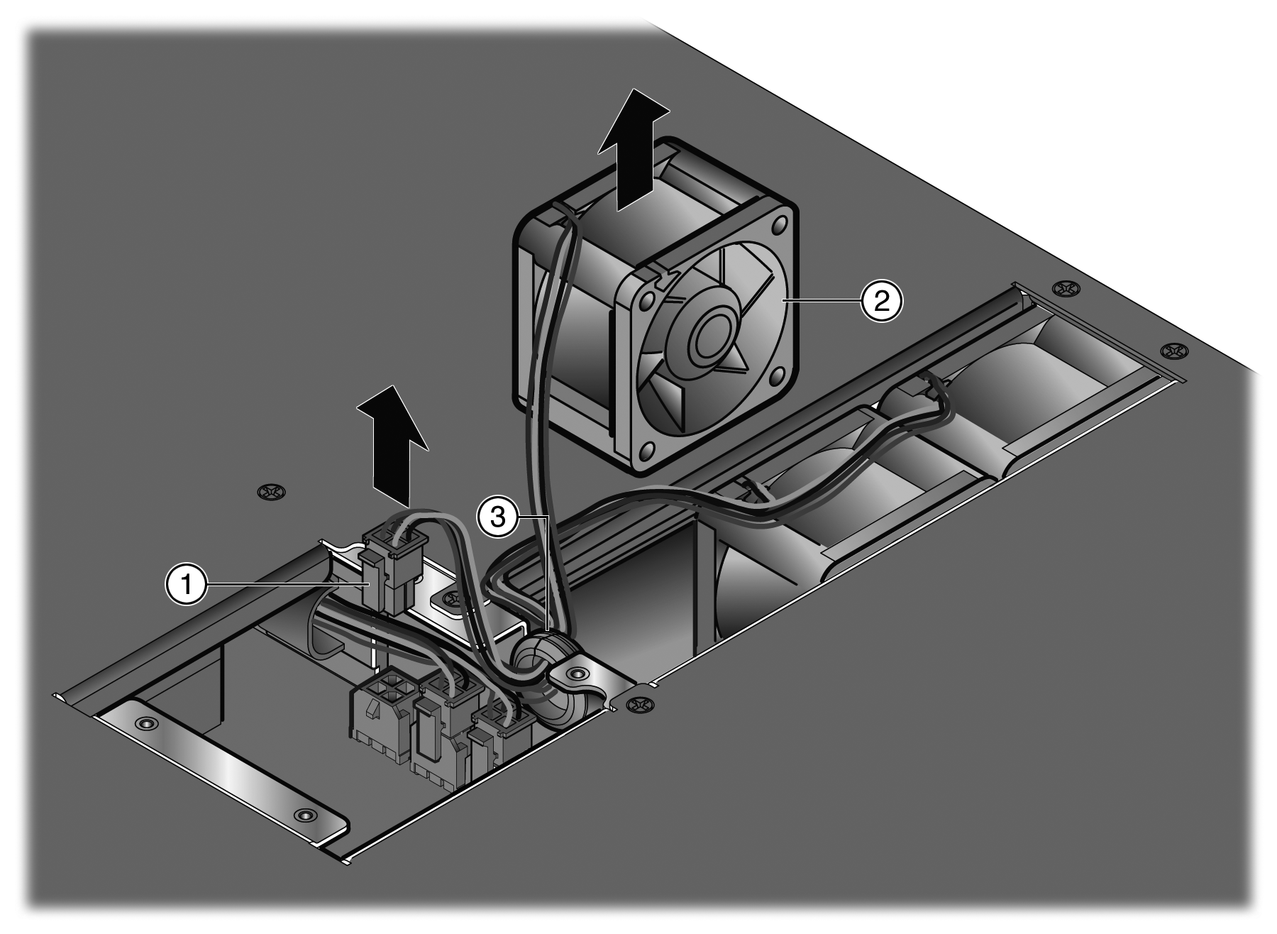
Remove the failed fan from
the SSA.
-
Lift the failed fan out the SSA.
-
Remove the failed fan‘s cables from the rubber grommet.
You might have to lift the rubber
grommet out of the chassis to remove the failed fan‘s cables from the grommet.
The grommet is slit.
-
Disconnect the fan from the appropriate connector.
The bank of F11-F13 connectors is
located next to fan F11, on the other side of the sheet metal wall that
separates the power supply bays from the rest of the SSA. If you are facing
toward the back of the SSA, the F11-F13 connectors are arranged as follows:
- F11
connector: left connector
- F12
connector: middle connector
- F13
connector: right connector
-
Unwind the replacement fan‘s cables.
-
Remove the cable clip from
the replacement fan.
-
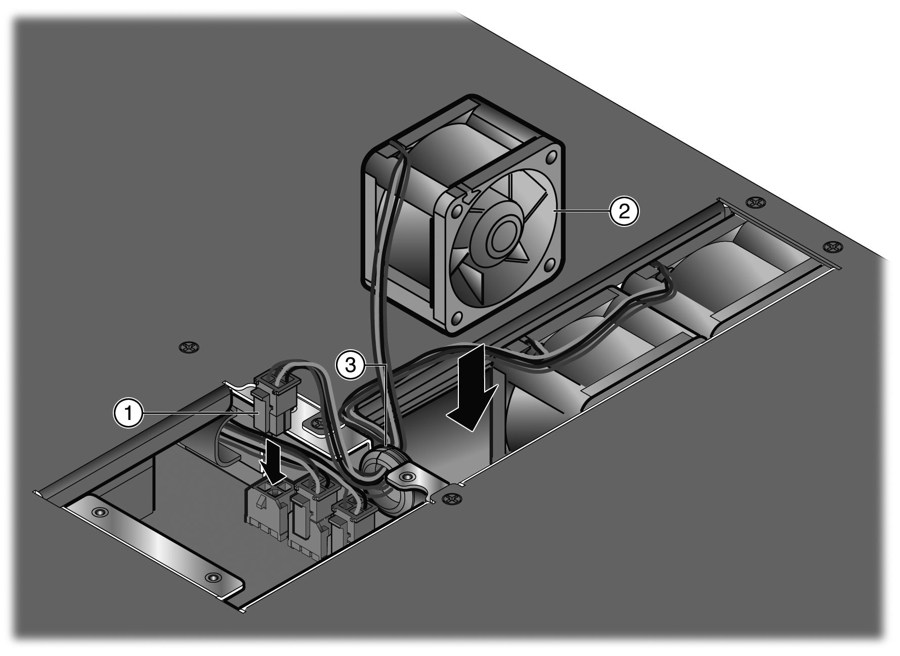
With the label side of the
replacement fan facing into the second power supply bay (labeled PS2) and the cable
on the left, slip the fan cable into the rubber grommet and connect the cable to the
chassis connector.
-
Position the fan in the SSA.
-
Position the cables of the F11-F13 fans on top of the fans, ensuring that the cables are not in a position that would cause the cables to be pinched by the rear panel.
-
Reinstall the rear panel of the SSA.
You can now reinstall the SSA in the equipment
rack.
 Print
this page
Print
this page Email this topic
 Feedback
 View PDF
 Download EPUB