Replacing Fans F1-F7
To replace an F1-F7 fan,
follow these steps:
-
Put on the ESD wrist strap and attach it to the ground receptacle on the front of the SSA.
-
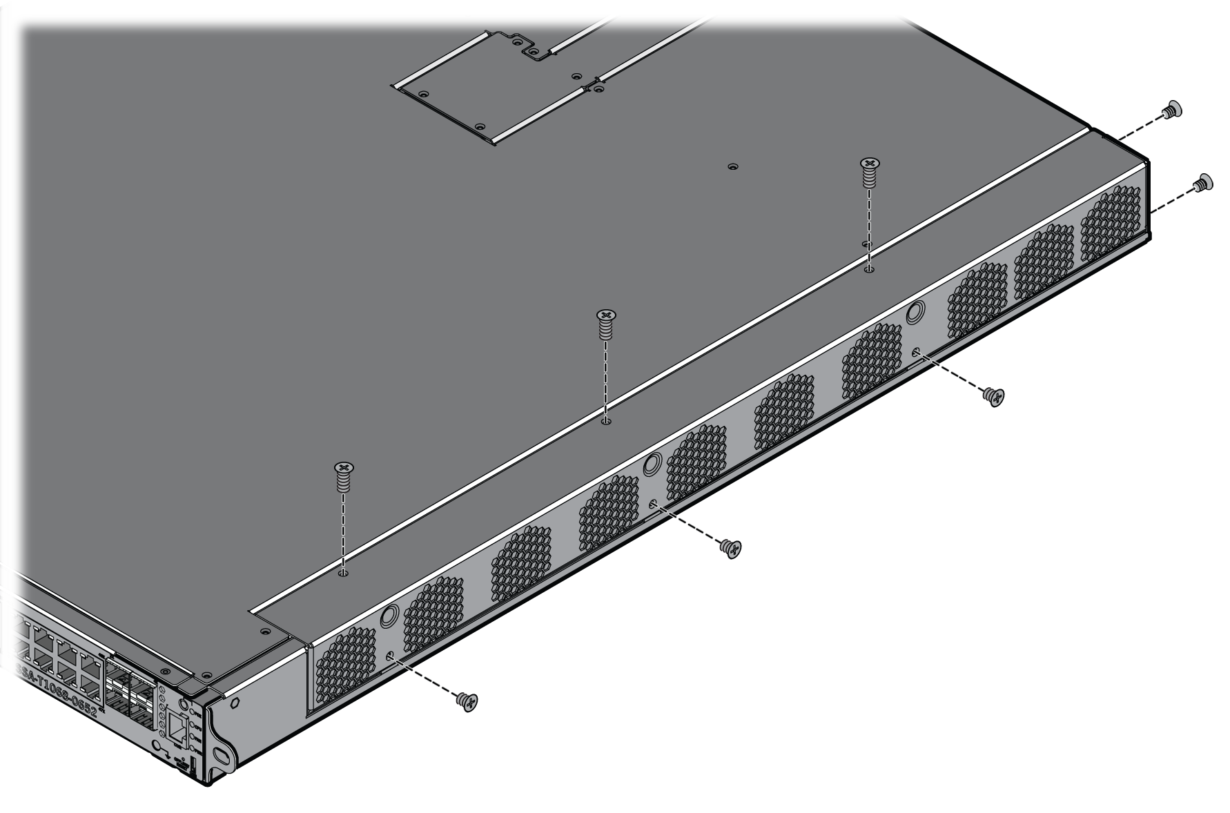
Remove the side panel from
the SSA by unscrewing the eight zinc (silver) screws from the side panel.
-
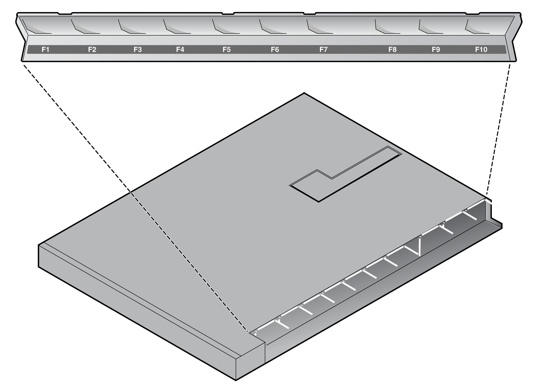
Set the side panel upside
down to view the label on the inside of the side panel that indicates the position of
each fan.
-
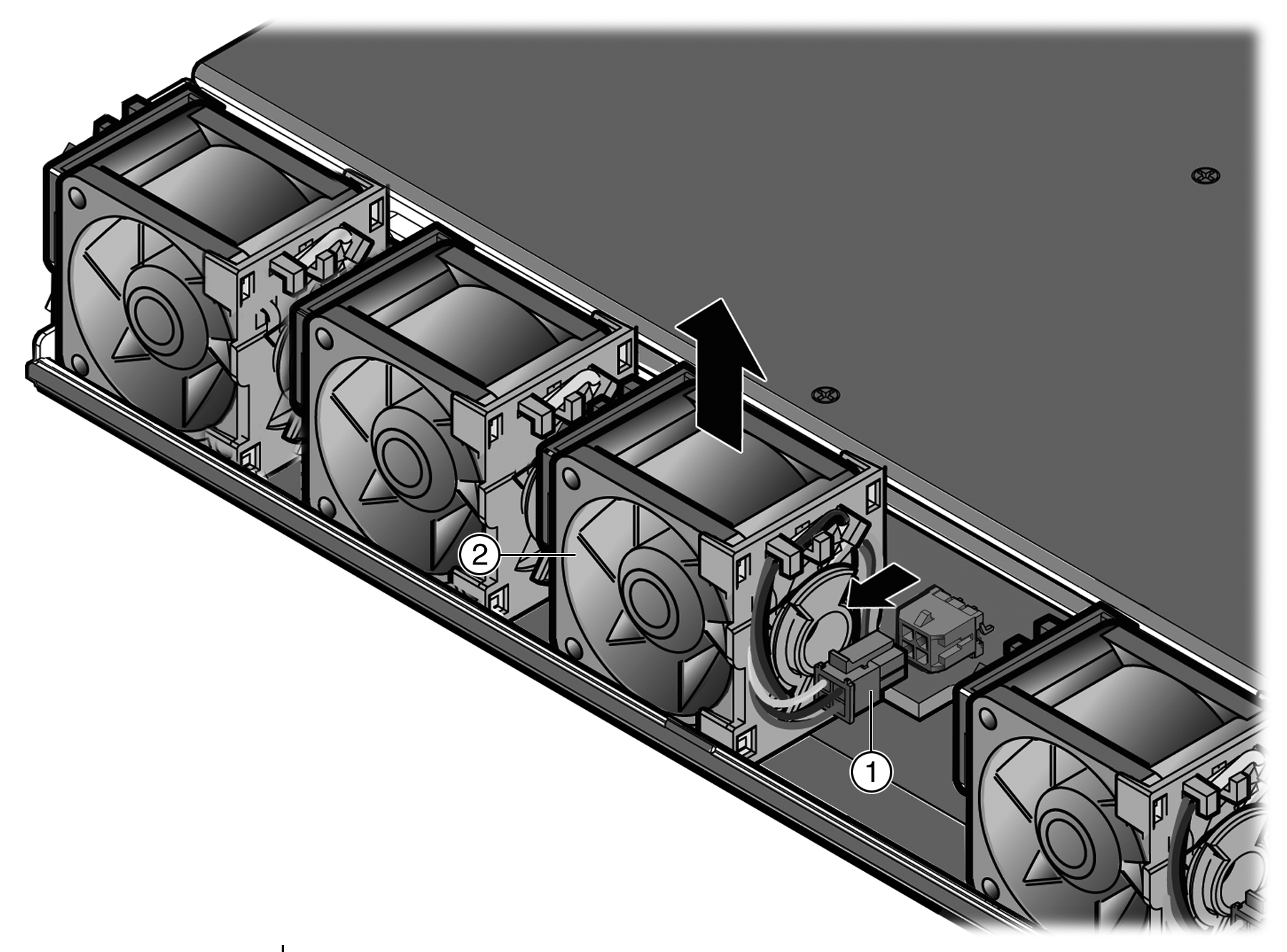
Remove the failed fan from its position in the SSA.
-
Disconnect the failed fan
from its connector, located to the right of the fan.
-
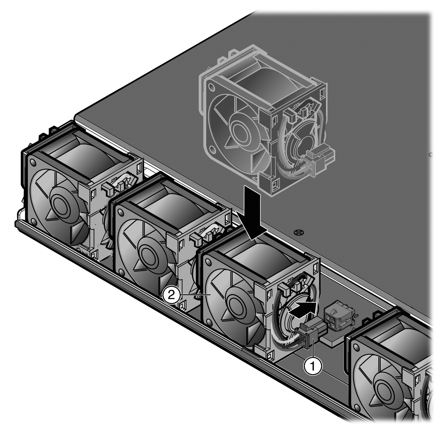
To ensure proper airflow,
connect the new fan to the chassis connector with the label side of the replacement
fan facing into the SSA and the cable clip on the right.
-
Place the fan in the chassis
next to the connector.
-
Reinstall the side panel of the SSA.
You can now reinstall the SSA in the equipment
rack.
 Print
this page
Print
this page Email this topic
 Feedback
 View PDF
 Download EPUB