The following tables show pinout assignments for connections between the COM port and a local management console.
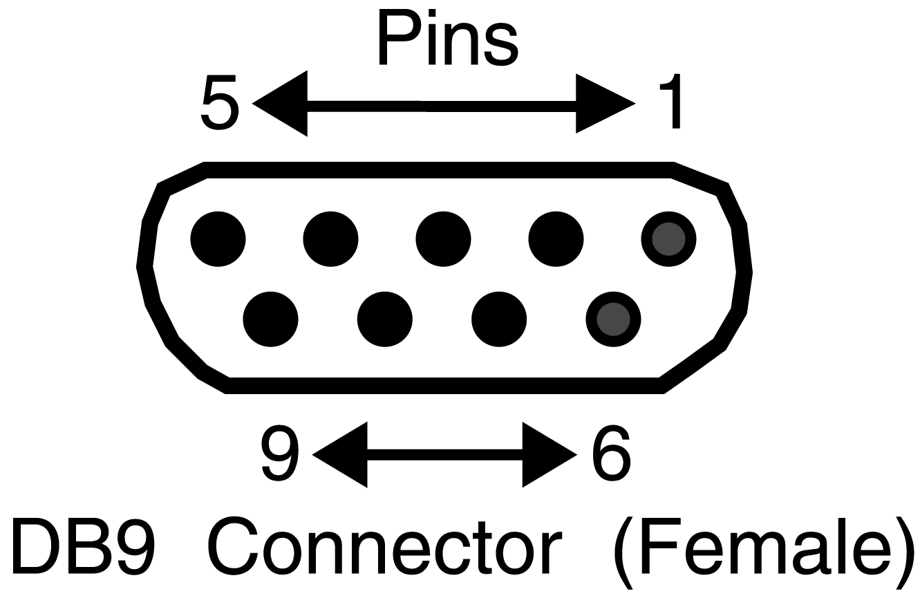
COM Port Adapter Wiring and Signal Diagram
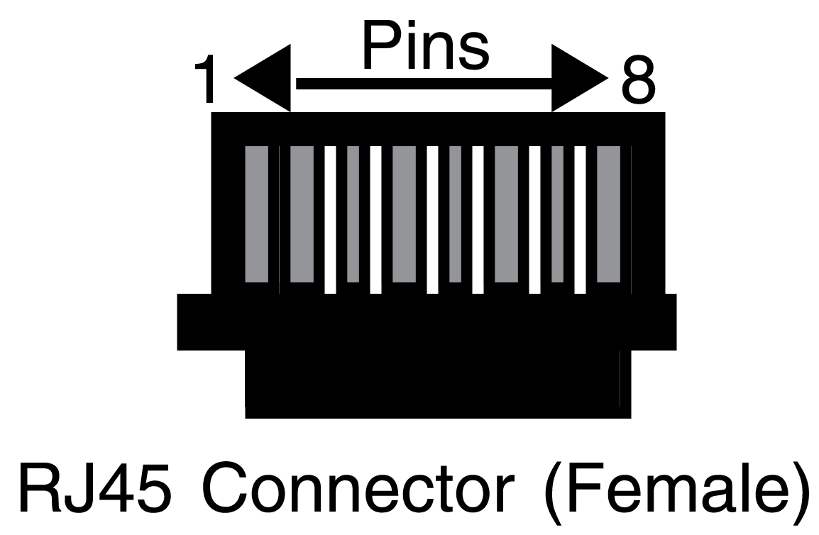
| RJ45 | DB9 | ||
|---|---|---|---|
| Pin | Conductor | Pin | Signal |
| 1 | Blue | 2 | Receive (RX) |
| 4 | Red | 3 | Transmit (TX) |
| 5 | Green | 5 | Ground (GRD) |
| 2 | Orange | 7 | Request to Send (RTS) |
| 6 | Yellow | 8 | Clear to Send (CTS) |
 |
 |
||
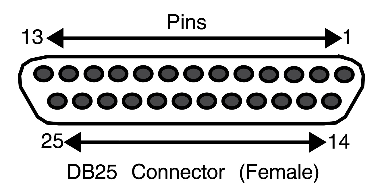
VT Series Port Adapter Wiring and Signal Diagram
| RJ45 | DB25 | ||
|---|---|---|---|
| Pin | Conductor | Pin | Signal |
| 4 | Red | 2 | Transmit (TX) |
| 1 | Blue | 3 | Receive (RX) |
| 6 | Yellow | 5 | Clear to Send (CTS) |
| 5 | Green | 7 | Ground (GRD) |
| 2 | Orange | 20 | Data Terminal Ready |
|
|
 |
||
 Print
this page
Print
this page Email this topic
 Feedback
 View PDF
 Download EPUB