System status LEDs are located on the front of the switch. The following figure shows the status LEDs for 5120 Series switches:
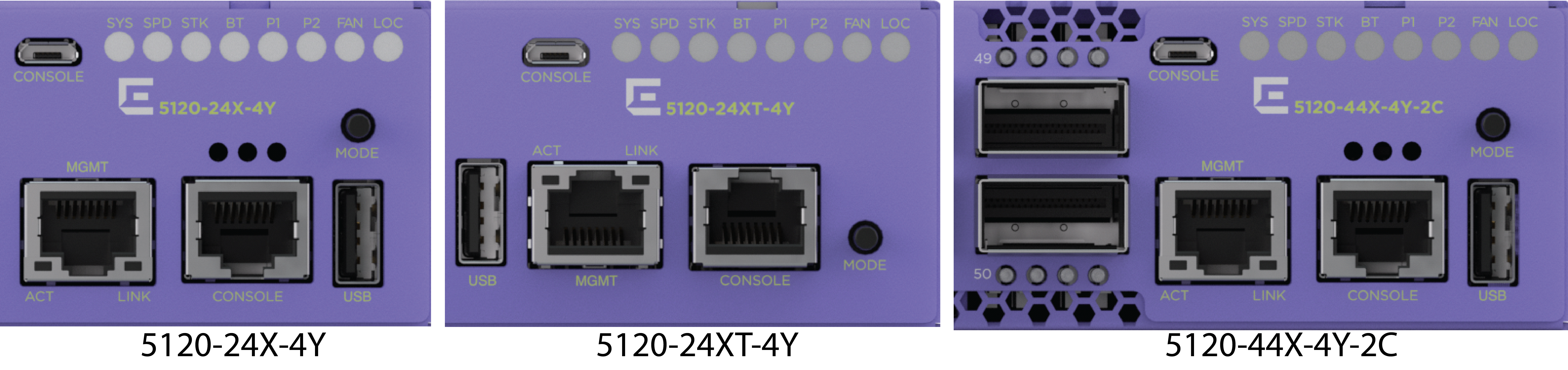
5120 Series front panel port LEDs, as described in the following table:
| LED | Color/State | Port State |
|---|---|---|
| SYStem status LED (Legacy MGMT function) | Slow Blinking Green | POST Passed, normal operation, blinks on standalone switch, stack primary and backup nodes in a stack; off for standby nodes in a stack |
| Blinking Green | POST in progress | |
| Blinking Amber | POST failed or overheat | |
| PSU status LEDs P1/P2 | Solid Green | Normal operation |
| Off | Not present | |
| Blinking Amber | Input or output power failure | |
| Speed status (SPD), Stacking status (STK) | SPD Solid Green | Speed mode |
| STK Solid Green | Stacking mode | |
| All Off | Normal mode | |
| Fan status LED | Solid Green | Normal operation |
| Blinking Amber | Fan failure | |
| Bluetooth Status LED (BT) | Blinking Green | Bluetooth pairing in progress |
| Solid Green | Bluetooth connected | |
| Off | Bluetooth not connected | |
| Locator LED (LOC) | Blinking Blue | Locator function |
Port LEDs can display in three different modes: SYS (the default mode), SPD (speed) and STK (stacking). The Mode button cycles through the three display modes. In the default SYS mode, SPD and STK are off. The port LEDs enter SPD display mode, indicated by the SPD LED, after pressing the Mode button one time. SPD mode helps to determine the operational speed of a port. The port LEDs enter the STK display mode, indicated by the STK LED, after pressing the Mode button a second time. STK mode is used to indicate slot presence and slot number through the first eight port LEDs. SPD and STK display modes expire after 30 seconds, and the display mode reverts back to the default SYS mode. A long press of the Mode button when in any mode other than STK mode initiates Bluetooth pairing.
The Mode button also supports the instant stacking feature. To instantly stack switches, first ensure that the SPD/STK LED is on STK by pressing the Mode button until the LED is green. Press and hold the Mode button for at least five seconds, then release the Mode button after five seconds. The front panel port LEDs on the primary node flash in an alternating pattern followed by a delayed reboot of all of the switches. The LEDs flash for approximately 15 seconds prior to the reboot. After the reboot completes, the switches are stacked.
SPD mode helps to determine the operational speed of a port.
| Color/State | Speed |
|---|---|
| Fast Blinking Green | 100Mbps |
| Solid Green | 1000Mbps |
| Slow Blinking Green | 10Gbps |
| Fast Blinking Green | 25Gbps |
|
Fast blinking amber |
5Gbps |
STK mode indicates slot presence and slot number through the first eight port LEDs. Pressing the Mode button for 5 seconds when in STK mode initiates InstStack auto-stacking.
| Port 1-8 Color/State | Stacking Indication |
|---|---|
| Steady Green | Slot corresponding to the port number of the LED is present. |
| Blinking Green | This slot has the slot number corresponding to the port number of the blinking LED. |
Each QSFP28 port has four green LEDs. The following table describes the states for the LEDs.
|
Port Configuration |
LEDs |
State |
Description |
|---|---|---|---|
|
100 Gb or 40 Gb |
1st LED |
Off |
No link. |
|
On |
Link is active, but there is no activity. | ||
|
Blinking |
Link is active and there is activity. | ||
|
All LEDs blinking (on 1 second, off 1 second) |
Switch is beaconing. | ||
|
25 Gb or 10 Gb |
All LEDs |
Off |
No link. |
|
On |
Link is active, but there is no activity. | ||
|
Blinking |
Link is active and there is activity. | ||
|
All LEDs blinking (on 1 second, off 1 second) |
Switch is beaconing. |
100/1000Base-T RJ-45 Management port on the front panel includes two LEDs located on each side of the RJ-45 port. The LED on the right side is labeled Link (for link status) and the LED on the left side is labeled Act (for port activity). The following table describes the meaning of the colors and states for the LEDs.
| Right-side LED | State | |
|---|---|---|
| Link | Solid Green | Link up |
| Off | No link up or port disabled. | |
| Left-side LED | State | |
| Act | Blinking Green | Packet transmitting or receiving. |
| Off | No packet transmitting or receiving. | |
[enable | disable] led locator