
Note
This topology is for only one BD. Since the DF state is selected per BD, another BD can use a different PE as the active node.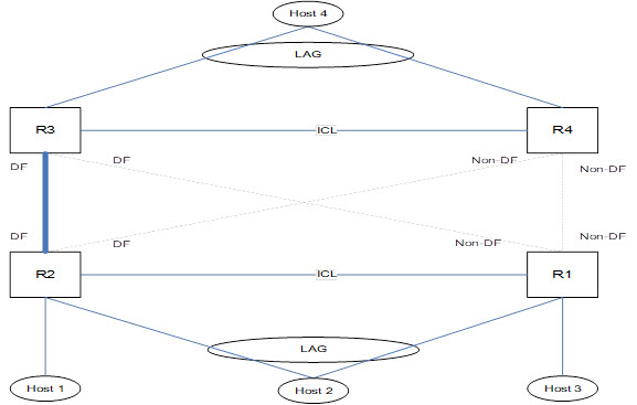
When VPLS MCT is activated, only one PW is operationally active between the MCT clusters, as represented by the solid line. The operational standby PW is represented by the dotted lines.
The ICL link between the MCT nodes is a VxLAN tunnel.