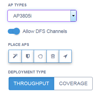
Access points with internal antennas can be placed automatically. We recommend using the AutoPlace APs option when you first place the APs and view the coverage in a heatmap.
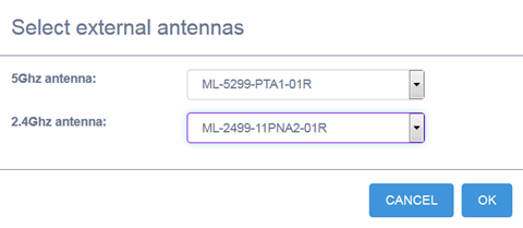
APs with external antennas and inventory that has been imported from an XML file, must be placed manually. Also, AP3916ic must be placed manually.
Based on the AP placements, the tool calculates how many users can be served given the application mix, and the device mix. (Device and application mix are set using the Venue Type option. Right-click on a floor to modify the Venue Type.)
To place the APs and sensors, and view coverage:
 .
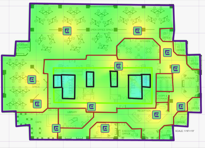
The APs are autoplaced on the floor image.
.
The APs are autoplaced on the floor image. . When the AP icon displays, place it in one or more positions on your
floor image.
. When the AP icon displays, place it in one or more positions on your
floor image. .The sensors are autoplaced on the floor
image.
.The sensors are autoplaced on the floor
image.
Note
To reduce the number of sensors, place your APs first, then add the sensors.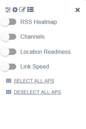
| RSS Heatmap | Displays the different values of RSS over the floor plan. From the top right corner of the screen, toggle between 5 GHz and 2.4 GHz bands and visualize the differences in the heatmap. |
| Channels | Displays a visualization of the channel plan. |
| Location Readiness | Use this option if location accuracy is important to you. Ideally, the floor plan coverage will appear completely green. |
| Link Speed | Displays the distribution of link speed. |
| BLE | Displays BLE coverage for 2.4 Ghz radios. |
 .
.
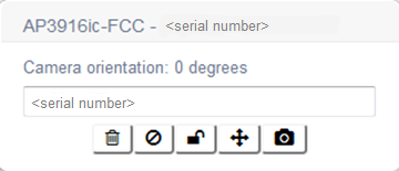
 - The Trash Can button
deletes the AP from the floor image.
- The Trash Can button
deletes the AP from the floor image. - The Exclude - button
excludes the AP from the coverage calculation.
- The Exclude - button
excludes the AP from the coverage calculation. - The Pin button locks and
unlocks the AP in a location on the floor image.
- The Pin button locks and
unlocks the AP in a location on the floor image. - The Orientation button
lets you configure the AP as a ceiling or wall mount installation. Default: Ceiling mount
- The Orientation button
lets you configure the AP as a ceiling or wall mount installation. Default: Ceiling mount - The Camera button is only
available for AP3916ic and lets you configure the angle of the camera,
which impacts the coverage calculation.. Select Wall Mount, then set
the AP height in meters. Select OK to save your
changes. to angle the camera towards the security
area. To do this, use your mouse to swing the purple arrow so that the
narrow end of the isosceles triangle is pointing towards the area that
you want to monitor. The camera angle is only representative of
orientation and does not account for obstructions that may exist.
- The Camera button is only
available for AP3916ic and lets you configure the angle of the camera,
which impacts the coverage calculation.. Select Wall Mount, then set
the AP height in meters. Select OK to save your
changes. to angle the camera towards the security
area. To do this, use your mouse to swing the purple arrow so that the
narrow end of the isosceles triangle is pointing towards the area that
you want to monitor. The camera angle is only representative of
orientation and does not account for obstructions that may exist.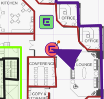
 Print
this page
Print
this page Email this topic
 Feedback
 View PDF
 Download EPUB