Draw the Inner Walls
Wall materials affect the propagation and estimation models.
Accurate representation of walls is essential for the accuracy of the model.
We recommend that you can draw inner walls for a
custom environment and configure material types, such as concrete around stairwells.
It is important that, at minimum, you draw inner walls that are made of concrete or
brick because these materials have a strong affect on the propagation. If
installation requires that an AP be placed within a walled area, then define both
walls on either side of the AP.

Note
If you do not want to
create a custom environment and draw the inner walls, you can select basic inner
wall types from the
Environment drop-down list instead, such as office drywalls or
cubicle walls. Office drywall has minimal impact on the RF Planner
propagation.
You can also draw exclusion zones. For example, you can exclude AP
placement from stairwells and washrooms/lavatories. The concrete walls for these
areas will still be included as part of the RF calculation, but APs will not be
automatically placed in the excluded zone.
To draw inner walls for a custom environment:
-
From the Tools menu, select Draw
Tools.
The Draw Tools dialog opens.
-
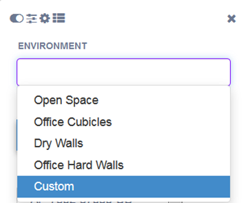
From the Draw Tools dialog,
under Environment, select Custom from the drop-down
list.
-
Under Draw Walls, select the
material type from the drop-down list (Drywall, Brick, Concrete, Glass), then
select
 .
.
The pen tool is
enabled.
-
To anchor the line drawing, double-click a corner
of an inner wall.
-
Click each corner of the inner wall, as needed, to
anchor the line and progress to the next corner.
-
When you are reach the end of the inner wall
boundary, double-click the last corner to anchor the line and disable the pen
tool.
Note
To change a wall type or to delete a
wall, right-click on a wall and choose the appropriate option from the menu
that displays. To modify a wall,

under
Draw
Walls.
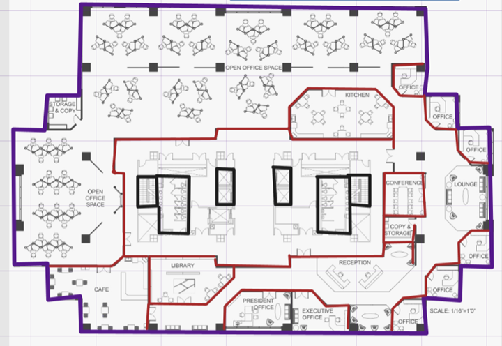
Inner Walls Drawn for Concrete and
Drywall
In this example, the concrete inner walls have black lines and the drywall
has red lines.
-
Repeat steps 3 - 6 for each area that you want to
customize.
-
(Optional) To exclude zones from your calculation,
under Draw Zones,
select
 and
draw a line around the areas that you want to exclude from AP placement.
and
draw a line around the areas that you want to exclude from AP placement.
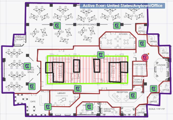
Excluded Zone - Indicated in Green
Area
-
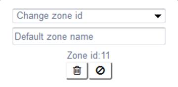
Right-click on the exclusion zone. In the Exclude Zone
dialog that displays, you must select
 to exclude
the zone from the calculations. You can also change the zone ID, give the zone a
default name, and delete the zone if needed.
to exclude
the zone from the calculations. You can also change the zone ID, give the zone a
default name, and delete the zone if needed.
 Print
this page
Print
this page Email this topic
 Feedback
 View PDF
 Download EPUB