This section describes a new AP-8533 installation with no
previous Access Point existing on the intended wall surface.
Procedure
-
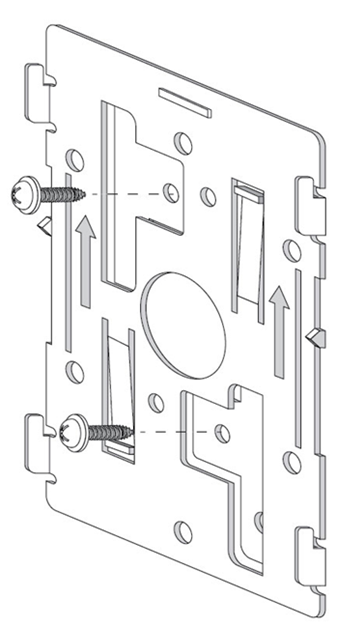
Place the mounting bracket against the wall.
-
Mark the screw hole locations depending on the intended deployment orientation
of the unit.

Note
When pre-drilling a hole, the recommended hole size is 4mm
(0.16in).
-
At each point, drill a hole in the wall and attach the mounting bracket.
-
Place the access point on the mounting
bracket.
-
To cable the access point using the Power Injector
solution (AP-PSBIAS-2P3-ATR), see Cabling the Access Point using Power Injector.
-
To cable the access point using the approved AP-8533 power supply
(PWR-BGA48V45W0WW), seeCabling the Access Point using Power Adapter.
-
Verify the access point is receiving power by
observing the LEDs are lit or flashing. For more information on AP-8533 LED
behavior, see LED
Indicators.
The access point is ready to
configure.

Caution
If not using an
AP-PSBIAS-2P3-ATR Power Injector, ensure only the AP-8533‘s designated power
supply (PWR-BGA48V45W0WW) is used to supply power to the Access Point. Using
an incorrectly rated power supply could damage the Access Point and void the
product warranty. Do not actually connect to the power source until the
cabling portion of the installation is complete.