The AP-8533 LED activity indicators are located on the front of the housing and are visible through the enclosure.
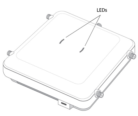
The LEDs display error conditions, transmission, and network activity for the 5 GHz 802.11ac (amber) radio, the 2.4 GHz 802.11n (green) radio, sensor radio (white), and the BLE radio (blue).
| State | 5 GHz Activity LED (Amber) | 2.4 GHz Activity LED (Green) | LED (Blue) | LED (White) |
|---|---|---|---|---|
| Firmware Update | On | Off | Off | Off |
| Normal Operation |
|
| N/A | N/A |
| Not Configured | On | On | N/A | N/A |
| Locate AP Mode | LEDs blink in an alternating green, amber, blue and white pattern using an irregular blink rate. This LED state in no way resembles normal operating conditions. | LEDs blink in an alternating green, amber, blue and white pattern using an irregular blink rate. This LED state in no way resembles normal operating conditions. | LEDs blink in an alternating green, amber, blue and white pattern using an irregular blink rate. This LED state in no way resembles normal operating conditions. | LEDs blink in an alternating green, amber, blue and white pattern using an irregular blink rate. This LED state in no way resembles normal operating conditions. |
| Sensor without SS connected | N/A | N/A | N/A | Off |
| Sensor with SS connected | N/A | N/A | N/A | On |
| Air Termination state | N/A | N/A | N/A | Blinking 0.5 seconds in 1 second duty cycle. |
| BT radio disabled | N/A | N/A | Off | N/A |
| BT radio enabled (operational) | N/A | N/A | On | N/A |