All installed fan modules must blow air in the same direction and must match the airflow direction of the installed power supplies. Before you begin, have the replacement fan module on hand so that you can complete the replacement promptly. The switch can overheat if left without adequate cooling for an extended time.
A fan tray with a blue tab indicates front-to-back airflow for switch cooling. Use a fan module labeled Air Out.
A fan tray with a green tab indicates back-to-front airflow for switch cooling. Use a fan module labeled Air In.
Note
The operating-system software cannot display the airflow direction.
Identify the Airflow Direction
The power supply and fan assemblies are identified by the following airflow directions:
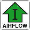
Intake power supply and fan assembly with an orange "I" label or without any label: Pulls air from the nonport-side of the switch and exhausts it out the port side.
Nonport-side air intake
Port-side air exhaust
Back-to-front (nonport-side to port-side) airflow
Part numbers ending with -R
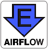
Exhaust power supply and fan assembly with a green "E" label: Pulls air from the port side of the switch and exhausts it out the nonport-side.
Nonport-side air exhaust
Port-side air intake
Front-to-back (port-side to nonport-side) airflow
Part numbers ending with -F
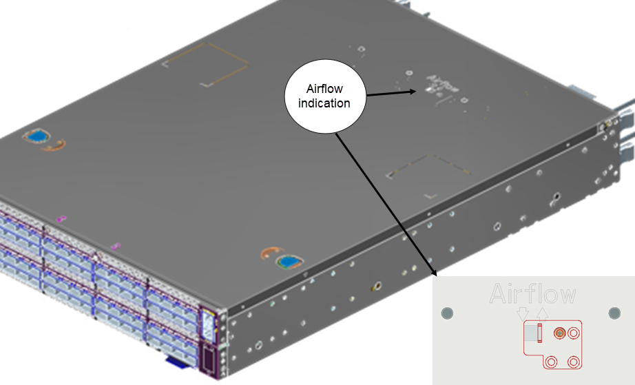
You can check the top view of the switch to ensure proper groove alignment: