
System status LEDs are located on the front of the switch. The following table describes the colors and the states for the LEDs.

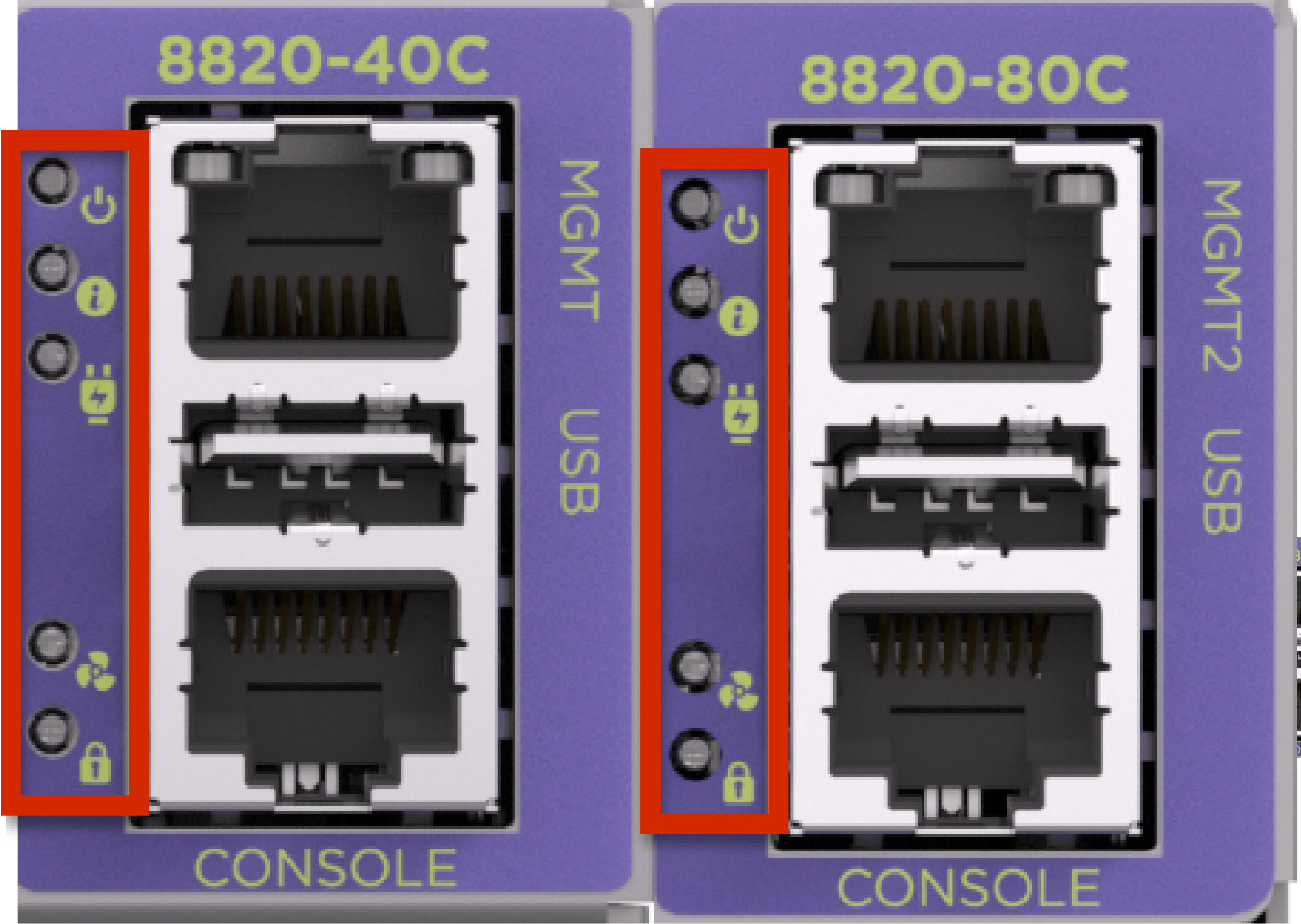
|
LED |
Color/State |
Description |
|---|---|---|
|
Power |
Solid green |
Valid power. All monitored voltages are nominal. |
|
Off |
No power. Some power rails are dropping below specification. | |
|
System |
Off |
The unit is not operational. |
|
Solid green |
Board is operational. | |
|
Blinking amber/green |
Attention (No definition). Controlled by SW. | |
|
Solid amber |
Fault/Initial state. This LED is lit during the reboot. | |
|
PSU Status |
Off |
No power. |
|
Solid green |
Power on. Main and Standby output enabled with no PSU warning or fault detected. | |
|
Solid amber |
Fault. Power supply fault. | |
|
Fan Status |
Off |
No power. |
|
Solid green |
All fans are operating normally. | |
|
Solid amber |
Fan failure. | |
|
Secure |
Off |
CeC1712 is booting up or fault. CeC1712 is performing the initial load (decrypt, validate, load) of its own code, prior to authenticating images. Or the CeC1712 was unable to decrypt, validate and load its own image. |
|
Slow blinking blue (1Hz) |
CeC1712 is authenticating or updating images. CeC1712 is currently authenticating or copying golden image to primary. | |
|
Fast blinking blue (4Hz) |
CeC1712 authentication failed. Neither primary nor golden image successfully validated. | |
|
Very slow blinking blue (0.25Hz) |
Bypass authentication. Bypassing authentication for test or development only. | |
|
Solid blue |
CeC1712 authentication complete. CeC1712 successfully authenticated the BIOS Flash-0 and BMC Flash-0 images. |