
Each port has one LED to indicate channel status. A channel selector switch enables you to display the status of individual channels. The selected channel is indicated in the display. The following table describes the states for the LED.

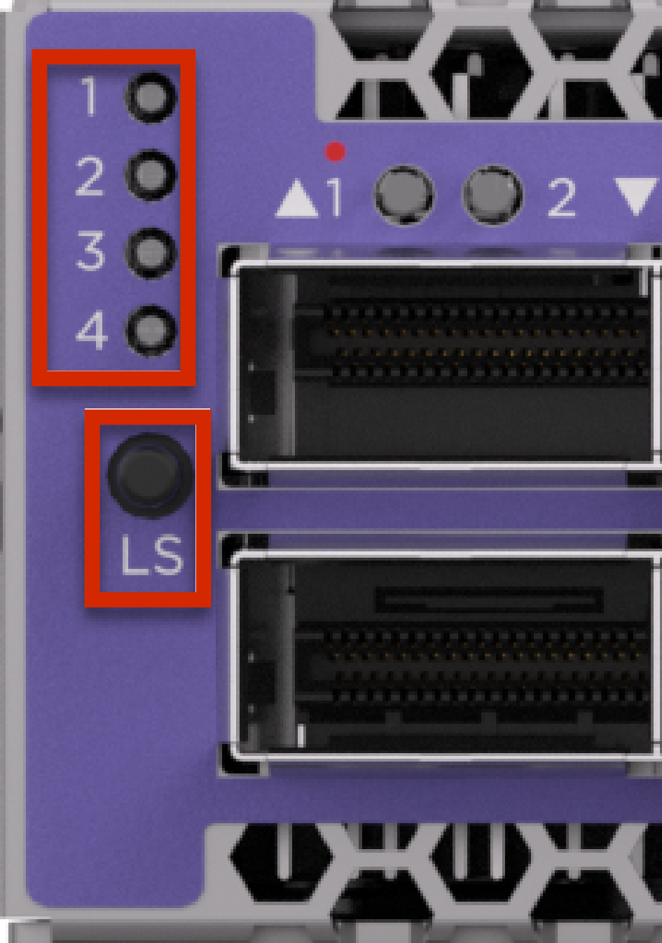
| 4 Bit Selector Panel (Bit 3, 2, 1, 0) | QSFP28 Channel | Description | Port LED (if Error) | Port LED (if no error) | |||
|---|---|---|---|---|---|---|---|
| 0 | 0 | 0 | 0 | 0 (Default) - Port and all channels | (Default) Indicate any error on port and all 4 lanes for any errors | Red or Yellow - if any error on port or any of the 4 lanes | Green - if no error on port and any of the 4 lanes |
| 0 | 0 | 0 | 1 | 1 | Indicate error on Lane 1 | Red or Yellow - if any error on lane 1 | Green - if no error on lane 1 |
| 0 | 0 | 1 | 0 | 2 | Indicate error on Lane 2 | Red or Yellow - if any error on lane 2 | Green - if no error on lane 2 |
| 0 | 1 | 0 | 3 | Indicate error on Lane 3 | Red or Yellow - if any error on lane 3 | Green - if no error on lane 3 | |
| 1 | 0 | 0 | 4 | Indicate error on Lane 4 | Red or Yellow - if any error on lane 4 | Green - if no error on lane 4 | |
The following are the port/channel LED indications:
| 100G | Link/Activity | Solid white | The port is linked |
| Blinking white | The port has link established and there is data activity | ||
| Off | No link | ||
| 40G | Link/Activity | Solid blue | The port is linked |
| Blinking blue | The port has link established and there is data activity | ||
| Off | No link | ||
| 25G | Link/Activity | Solid amber | The port is linked |
| Blinking amber | The port has link established and there is data activity | ||
| Off | No link | ||
| 10G | Link/Activity | Solid green | The port is linked |
| Blinking green | The port has link established and there is data activity | ||
| Off | No link | ||
| Fault | Fault detected | Solid red | Local fault detected |
| Blinking red | Remote fault detected. |