
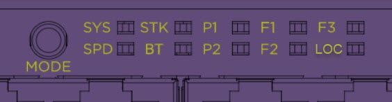
System status LEDs are located on the panel front of the switch. The following table describes the colors and the states for the LEDs.
|
LED |
Color/State |
Port State |
|---|---|---|
|
SYStem status LED (Legacy MGMT function) |
Slow blinking green |
POST Passed, normal operation, blinks on standalone switch, stack master, and backup nodes in a stack; off for standby nodes in a stack |
|
Blinking green |
POST in progress | |
|
Blinking amber |
POST failed or overheat | |
|
PSU status LEDs P1/P2 |
Solid green |
Power On |
|
Off |
Power off and no power attached | |
|
Blinking amber |
Power supply failures | |
|
Fan status LEDS (F1, F2 and F3) |
Solid green |
Normal operation |
|
Blinking amber |
Fan failure | |
| Amber | Fan absent | |
|
Bluetooth Status LED (BT) |
Blinking green |
Bluetooth pairing in progress |
|
Solid green |
Bluetooth connected | |
|
Locator LED (LOC) |
Blinking blue |
Locator function |
|
Ethernet Port 1-24 or 1-48 | ||
|
VIM5 Port 25-32 or 49-56 |
Port LEDs can display in two different modes: SYS and SPD. The Mode button cycles through the two display modes. In the default SYS mode, SPD is off. The port LEDs enter SPD display mode, indicated by the SPD LED, after pressing the Mode button one time. SPD mode helps to determine the operational speed of a port. SPD display mode expires after 30 seconds, and the display mode reverts back to the default SYS mode.


Note
Front-panel PoE ports use Amber to indicate PoE states.
In the default SYS mode, SPD is OFF, and the port status displays behavior for link, traffic, and POE as described in the following table:
|
Color/State |
Meaning |
|---|---|
|
Solid green |
Link is OK; port is not powered |
|
Solid amber |
Link is OK; port is powered; no traffic |
|
Blinking green |
Link is OK and transmitting packets; port is not powered |
|
Blinking amber |
Link is OK and transmitting packets; port is powered |
|
Slow blinking amber |
No link, or disabled port; port is powered |
|
Alternating amber and green |
Port has a power fault |
|
Slow blinking green |
Admin disabled and no power |
|
Off |
Port is not powered, has no link, or is disabled |
After one press of the Mode button (see VSP 4900 Series Mode and System Status LEDs), the port LEDs enter the SPD display mode, indicated by the SPD LED. SPD mode is used to help determine the operational speed of a port. Color and blink pattern indicate speeds, as referenced by the following table:
|
Color/State |
Speed |
|---|---|
|
Blinking amber |
2.5Mbps |
|
Slow blinking green |
5Mbps |
|
Solid green |
10Mbps |
|
Blinking green |
100Mbps |
|
Solid amber |
1000Mbps |
|
Solid green |
10Gbps |
|
Blinking amber |
25Gbps |
|
Blinking green |
40Gbps |