The following figure displays back panel features of the C5110. C5110 Back Panel Features depicts the features and functions of the C5110 back panel.
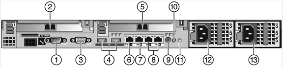
C5110 Back Panel Features
| Callout | Feature | Function |
|---|---|---|
| 1 | Serial port connector | Console Port – Used to get into Rescue mode. |
| 2 | PCIe1 fiber optic connector | Data port – esa1 |
| 3 | Video connector | Not used in the current release |
| 4 | USB connector (2) | Connects USB 2.0-compliant devices to the system. For more information, see the Note below. |
| 5 | PCIe2 fiber optic connector | Data port – esa2 |
| 6 | NIC1 connector | Management port – eth0 |
| 7 | NIC2 connector | Data port – esa0 |
| 8 | Remote Access Controller | Not used in the current release. |
| 9 | System status indicator connector | Not used in the current release. |
| 10 | System status indicator | The blue-colored system status indicator blinks to indicate the location of a particular system within a rack. The indicator continues to blink until one of the system identification button is pushed again. |
| 11 | System identification button | The identification buttons on the front and back panels can be used to locate a particular system within a rack. When one of these buttons is pushed, the blue system status indicator on the front and back blinks until one of the buttons is pushed again. |
| 12 | AC Power Supply 1 | AC Power Supply 1 and 2 combine to make a redundant power supply. |
| 13 | AC Power Supply 2 |

Note
The PCIe and PCIe2 ports are fiber optic ports. If your infrastructure does not allow the fiber optic connection, you must get a Gigabit Media Converter to convert the fiber optic connection to a copper Gigabit connection. For example, use a converter that receives the fiber optic connection and outputs traffic via the RJ45 copper port (Unshielded Twister Pair – UTP). Print
this page
Print
this page Email this topic
 Feedback
 View PDF
 Download EPUB