E4G-200 Clock Module RJ-45 Connector
| Pin | Description | Direction | Comment |
|---|---|---|---|
| 1 | BITS_IN_P | In | 1.544 MHz, 2.048 MHz RS-422 |
| 2 | BITS_IN_N | In | 1.544 MHz, 2.048 MHz RS-422 |
| 3 | 1_PPS_P | Out | 1 PPS RS-422 |
| 4 | — | — | |
| 5 | — | — | |
| 6 | 1_PPS_N | Out | 1 PPS RS-422 |
| 7 | ToD_N | I/O | RS-422 |
| 8 | ToD_P | I/O | RS-422 |
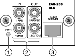
Signals for the E4G-200 Mini-BNC Connectors
| Connector Position | Label | |
|---|---|---|
| IN | OUT | |
| Upper | 1 PPS input, 3.3 V level | 1 PPS/8 KHz frame output, 3.3 V level |
| Lower | 10-Mhz clock input, 3.3 V level | 1.5 MHz/2 MHz/10 MHz clock output, 3.3 V level |
Pinouts for the E4G-200 F16T1E1 Module
| Pin | Description |
|---|---|
| 1 | RX_RING |
| 2 | RX_TIP |
| 3 | — |
| 4 | TX_RING |
| 5 | TX_TIP |
| 6 | — |
| 7 | — |
| 8 | — |
RJ-45 Console Port on the E4G-200 Router
| Function | Pin Number | Direction |
|---|---|---|
| CTS (clear to send) | 1 | In |
| DTR (data carrier detect) | 2 | Out |
| TXD (transmit data) | 3 | Out |
| GND (ground) | 4 | — |
| GND (ground) | 5 | — |
| RXD (receive data) | 6 | In |
| DSR (data set ready) | 7 | In |
| RTS (request to send) | 8 | Out |
Pinouts for an RJ-45 to DB-9 Adapter
| Signal | RJ-45 Pin | DB-9 Pin |
|---|---|---|
| CTS (clear to send) | 1 | 8 |
| DTR (data carrier detect) | 2 | 6 |
| TXD (transmit data) | 3 | 2 |
| GND (ground) | 4 | 5 |
| GND (ground) | 5 | 5 |
| RXD (receive data) | 6 | 3 |
| DSR (data set ready) | 7 | 4 |
| RTS (request to send) | 8 | 7 |
Pinouts for a T1/E1 RJ-48C Crossover Cable
| RJ-48C Connector Pin | Description | RJ-48C Connector Pin |
|---|---|---|
| 1 | RX_RING to TX_RING | 4 |
| 2 | RX_TIP to TX_TIP | 5 |
| 3 | — | 6 |
| 4 | TX_RING to RX_RING | 1 |
| 5 | TX_TIP to RX_RING | 2 |
| 6 | — | 3 |
| 7 | — | — |
| 8 | — | — |
 Print
this page
Print
this page Email this topic
 Feedback
 View PDF
 Download EPUB