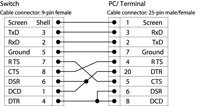
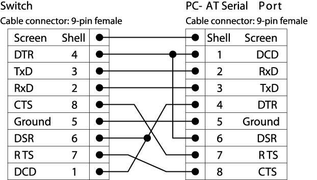
Pinouts for the DB-9 Console Connector
| Function | Pin Number | Direction |
|---|---|---|
| DCD (data carrier detect) | 1 | In |
| RXD (receive data) | 2 | In |
| TXD (transmit data) | 3 | Out |
| DTR (data terminal ready) | 4 | Out |
| GND (ground) | 5 | — |
| DSR (data set ready) | 6 | In |
| RTS (request to send) | 7 | Out |
| CTS (clear to send) | 8 | In |
Port Mapping between the E4G-B16T1E1 MRJ21 Connectors and T1/E1 Ports
| MRJ21 Connector 1 | MRJ21 Connector 2 |
|---|---|
| Port 1 | Port 9 |
| Port 2 | Port 10 |
| Port 3 | Port 11 |
| Port 4 | Port 12 |
| Port 5 | Port 13 |
| Port 6 | Port 14 |
| Port 7 | Port 15 |
| Port 8 | Port 16 |
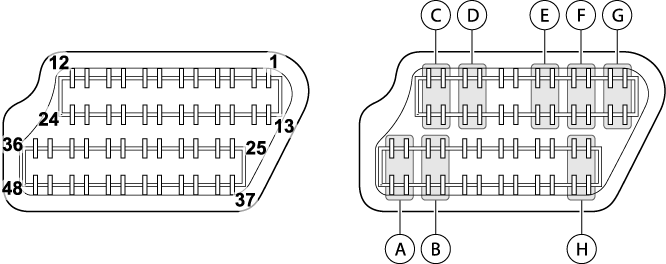
| A = Port 1 or 9 | E = Port 5 or 13 |
| B = Port 2 or 10 | F = Port 6 or 14 |
| C = Port 3 or 11 | G = Port 7 or 15 |
| D = Port 4 or 12 | H = Port 8 or 16 |
MRJ21 Connector Pinouts
| T1/E1 Port Number | Signal | Pin Number | T1/E1 Port Number | Signal | Pin Number |
|---|---|---|---|---|---|
| Port 1 or 9 | RX-Ring | 35 | Port 5 or 13 | RX-Ring | 5 |
| RX-Tip | 36 | RX-Tip | 6 | ||
| TX-Ring | 48 | TX-Ring | 18 | ||
| TX-Tip | 47 | TX-Tip | 17 | ||
| Port 2 or 10 | RX-Ring | 33 | Port 6 or 14 | RX-Ring | 3 |
| RX-Tip | 34 | RX-Tip | 4 | ||
| TX-Ring | 46 | TX-Ring | 16 | ||
| TX-Tip | 45 | TX-Tip | 15 | ||
| Port 3 or 11 | RX-Ring | 11 | Port 7 or 15 | RX-Ring | 1 |
| RX-Tip | 12 | RX-Tip | 2 | ||
| TX-Ring | 24 | TX-Ring | 14 | ||
| TX-Tip | 23 | TX-Tip | 13 | ||
| Port 4 or 12 | RX-Ring | 9 | Port 8 or 16 | RX-Ring | 25 |
| RX-Tip | 10 | RX-Tip | 26 | ||
| TX-Ring | 22 | TX-Ring | 38 | ||
| TX-Tip | 21 | TX-Tip | 37 |
Pinouts for the Fan-out Cable RJ-48C Connector
| Pin | Description |
|---|---|
| 1 | RX_RING |
| 2 | RX_TIP |
| 3 | Shield/Ground |
| 4 | TX_RING |
| 5 | TX_TIP |
| 6 | Shield/Ground |
| 7 | — |
| 8 | — |
 Print
this page
Print
this page Email this topic
 Feedback
 View PDF
 Download EPUB