The following figure is an example of an autonomous system using OSPF routers. The details of this network follow.
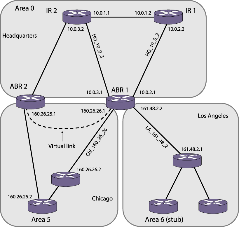
Area 0 is the backbone area. It is located at the headquarters and has the following characteristics:
Area 5 is connected to the backbone area by way of ABR 1 and ABR 2. It is located in Chicago and has the following characteristics:
Area 6 is a stub area connected to the backbone by way of ABR 1. It is located in Los Angeles and has the following characteristics:
The following section provides two router configurations for the example shown in the above figure.
 Print
this page
Print
this page Email this topic
 Feedback
 View PDF
 Download EPUB