QoS Traffic Shaping Basic
Configuration
The WiNG software uses different Quality of Service (QoS)
screens to define WLAN and device radio QoS configurations. The is separate from WLAN and radio QoS configurations, and is used to
configure the priority of the different DSCP packet types.
QoS values are required to provide priority of service to some packets over others.
For example, VoIP packets get higher priority than data packets to provide a better
quality of service for high priority voice traffic.
The profile QoS screen maps the 6-bit Differentiated Service Code
Point (DSCP) code points to the older 3-bit IP Precedent field located in
the Type of Service byte of an IP header. DSCP is a protocol for specifying and
controlling network traffic by class so that certain traffic types get precedence.
DSCP specifies a specific per-hop behavior applied to a packet.
To define an QoS configuration for DSCP mappings:
-
Go to .
The Device
Configuration screen displays. This screen lists wireless
controllers, service platforms and access points within the managed
network.
-
Select a device from the list
displayed.
The selected device's configuration screen displays.
-
Expand the Network node and
select Quality of
Service (QoS).
The Traffic
Shaping screen displays with the Basic
Configuration tab selected by default.
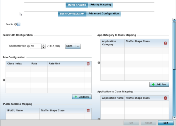
Profile Overrides -
Network QoS Traffic Shaping Basic Configuration Screen
-
Select Enable to provide
traffic shaping using the defined bandwidth, rate and class mappings.
Apply traffic shaping to specific applications to apply application
categories. When application and ACL rules are conflicting, applications
have priority, followed by application categories, then ACLs.
-
Set the Total Bandwidth
configurable for the traffic shaper. Set the value from either 1 - 1,000 Mbps,
or from 250 - 1,000,000 Kbps.
-
Select + Add Row within
the Rate
Configuration table to set the Class Index (1 - 4) and Rate (in
either Kbps, Mbps or percentage) for the traffic shaper class. Use the rate
configuration to control the maximum traffic rate sent or received on the
device. Consider this form of rate limiting on interfaces at the edge of a
network to limit traffic into or out of the network. Traffic within the set
limit is sent and traffic exceeding the set limit is dropped or sent with a
different priority.
-
Refer to the
IP ACL Class Mapping table and select
+ Add
Row to apply an IPv4 formatted ACL to the
shaper class mapping. Select + Add
Row to add mappings. For more information on
creating IP based firewall rules, refer to Configuring IP Firewall Rules
and Setting an IPv4 or IPv6 Firewall Policy.
-
Refer to the
IPv6 ACL Class Mapping table and select
+ Add
Row to apply an IPv6 formatted ACL to the
shaper class mapping. Select + Add
Row to add mappings. For more information on
creating IP based firewall rules, refer to Configuring IP Firewall Rules
and Setting an IPv4 or IPv6 Firewall Policy.
-
Refer to the
App-Category to Class Mapping table and
select + Add Row to apply an application category to shaper
class mapping. Select + Add Row to add mappings by selecting
the application category and its traffic shaper class. For more information on
creating an application category, refer to Create a Custom Application Definition.
-
Refer to the
Application to Class Mapping table and
select + Add Row to apply an application to shaper class
mapping. Select + Add
Row to add mappings by selecting the
application and its traffic shaper class. For more information on
creating an application, refer to Create a Custom Application Definition.
-
Click the OK button located
to save the changes to the traffic shaping basic configuration.
Click Reset to revert to the last saved configuration.
 Print
this page
Print
this page Email this topic
 Feedback
 View PDF
 Download EPUB