Connecting the RPS Cable and AC Power Cord to an RPS-500p
Connect the RPS-500p power supply to the PoE-compliant switch
using the supplied RPS cable, as follows.

Caution
Observe all
precautions when handling sensitive electronic
equipment.
- Connect one end of the
RPS cable to the Redundant Power Supply connector at the rear of the power supply.
-
Connect the other end of the RPS cable to the Redundant
Power Supply connector on the switch.
See
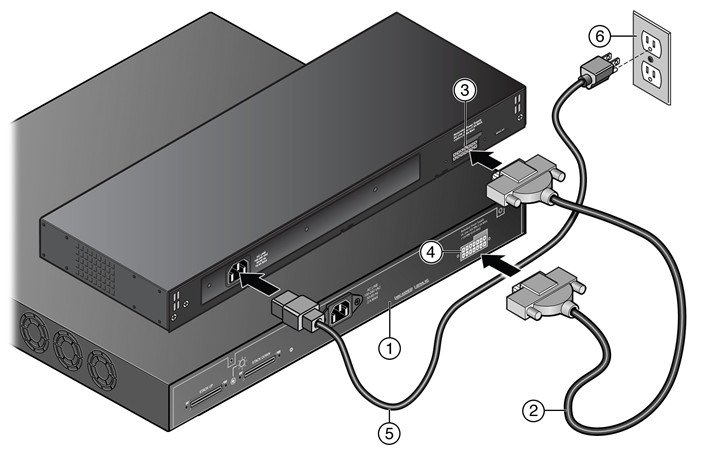
RPS Cable and AC Power Cord Connections for the RPS-500p.
RPS Cable and AC Power Cord Connections for
the RPS-500p
| 1 = PoE-compliant switch |
4 = Redundant Power Supply connector
on switch |
| 2 = RPS cable |
5 = AC power cord |
| 3 = Redundant Power Supply connector
on power supply |
6 = AC power outlet with ground
connection |

Note
AC power cords and outlets vary
depending on country.
- Connect the AC power cord to the AC input power
connector on the power supply.
-
Plug the AC power cord into
the main AC power outlet.
The AC power LED on the front of the RPS-500p turns green to indicate that the
connection was successful and the power supply is operating properly.
If the LED does not light properly, follow these steps to
troubleshoot:
- Check the AC power cord connection at the AC power source and make
sure the power source is within specification.
- Check the AC power connection to the power supply.
- Swap the AC power cord with one that is known to work
properly.
 Print
this page
Print
this page Email this topic
 Feedback
 View PDF
 Download EPUB