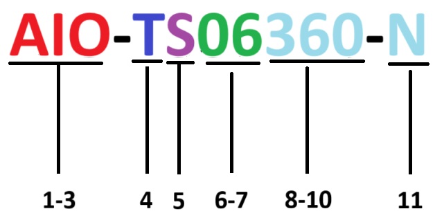
Each Extreme Networks antenna is identified by an alphanumerical code called a part number or P/N. Each P/N is broken into 3 fields separated by a dash (-), with each number or letter identifying an important feature of the antenna.
Use the following key to read or decode an antenna P/N.
| Field | Position | Meaning |
|---|---|---|
| Field 1 | Position 1 -3 | The environment in which the antenna can be used:
Note: Some AIO - indoor and outdoor - antennas have a RP-SMA connector, which has to be weatherized before you use them outdoors. Check the connector type before you deploy outdoors.
|
| Field 2 | Position 4 | The bandwidth:
|
| Position 5 | The feed:
| |
| Position 6-7 | Gain in dBi:
Note: In some P/Ns, you may see 75, which denotes a dBi of 7.5.
| |
| Position 8-10 | 3dBi beam width in degrees.
| |
| Field 3 | Position 11 | The connector type:
|