SSA switch System LEDs shows the system LEDs. The two left LEDs are separately labeled for fan modules 1 and 2.
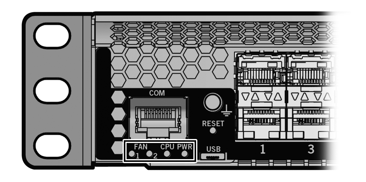
System LEDs describes the LED indications for the system LEDs and provides recommended actions.
System LEDs
| LED | Color | State | Recommended Action |
|---|---|---|---|
| FAN 1 and 2 | Off | Fans are off or booting up. | None |
| Green | All fans are operating normally. | None | |
| Amber | One fan has failed. | Replace the failed fan. See Replacing the SSA Fan Module. | |
| Red | One or more of the following conditions has occurred:
|
Use the show system CLI command to check the
exact condition of the fans. If fans have failed, replace the fan module. See Replacing the SSA Fan Module. |
|
| CPU | Off | Power off. | Ensure that the chassis has adequate power. |
| Amber | Blinking: Device in bootup process. | None | |
| Solid: Testing. | If the LED remains amber for several minutes, contact us for technical support. | ||
| Green | Blinking: Image starts running. | None | |
| Solid: Functional. | None | ||
| Red | Solid: Processor in reset. | None | |
| Green and Amber | Blinking: The SSA switch is in the process of shutting down. | None. This state is activated when the RESET button is pressed for less than one second to start an orderly shutdown. | |
| Amber and off | Alternating (67% on, 33% off): A shutdown is complete. The indication holds for 60 seconds and restarts automatically. | While in this state, you have 60 seconds before the SSA switch reboots. | |
| Blue | Blinking: Virtual Switch Bonding is enabled, but the devices are not bonded | None | |
| Solid: Virtual Switch Bonding is enabled, and the devices are bonded. | None | ||
| PWR | Off | The SSA switch is not receiving power from the power supplies. | Ensure that the power cords are plugged in and that
power is available at the source. Contact us for technical support. |
| Green | Functional. Indicates one of the following conditions:
|
None | |
| Amber | One of the following conditions has occurred:
|
Ensure that the power cords are plugged in and that
power is available at the source. Contact us for technical support. |

Note
The PWR LED status indication is based on power supplies being powered on.CPU LED in Virtual Switch Bonding (VSB) Configuration describes the CPU LED when the SSA switch is in a virtual switch bonding configuration.
CPU LED in Virtual Switch Bonding (VSB) Configuration
| Color | State |
|---|---|
| Green and Blue | Blinking: Image has started and found chassis bonding enabled. |
| Blue | Solid: Functional: binding is operational and ready to switch. |
| Blue | Blinking: Binding is not functional (non-operational). |
 Print
this page
Print
this page Email this topic
 Feedback
 View PDF
 Download EPUB