The following image illustrates a sample topology for a redundant Tunnel Concentrator deployment where ExtremeCloud IQ (Classic) is the management application. This deployment requires that you have two Tunnel Concentrator instances that are installed on different appliances.

The following table summarizes the IP address settings from the example. The table also indicates which application gets used to assign each address and when the addresses are assigned.
| Universal Compute Platform | Tunnel Concentrator | ExtremeCloud IQ | ||||
|---|---|---|---|---|---|---|
| Hostname | IP Address | Virtual IP on data port (uses VRRP) | Assigned Virtual IP Address | Tunnel IP Address (uses VRRP) | Redundant Tunnel Concentrators | IP Address (for tunnel termination) |
| UCP-01 | 10.10.10.1 | 10.10.10.2 | 10.10.10.2 | 10.10.10.112 | Primary | 10.10.10.4 |
| UCP-02 | 10.10.10.60 | 10.10.10.61 | 10.10.10.61 | Backup | 10.10.10.62 | |
| Assigned during ExtremeCloud Edge setup on Universal Compute Platform (prior to Tunnel Concentrator installation). | Assigned during Tunnel Conc. install. Uses data port virtual IP. | Assigned on ExtremeCloud IQ during tunnel provisioning stage (after Tunnel Concentrator installation). | ||||
This example uses an alternative configuration flow that differs from the configuration that is presented in the ExtremeCloud IQ (Classic) Configuration chapter. Because the configuration example does not use Layer 2 roaming or a tunnel policy, you can complete the configuration from the network policy by drilling down into multiple configuration layers, assigning settings, and then reversing out, while saving the configuration in the reverse order from which it was applied.
The following image illustrates the configuration flow for this example.

You require two new Tunnel Concentrator installations (TC-01 and TC-02) that are installed on different appliances, but which are not onboarded to ExtremeCloud IQ.
You require existing Network Policy and SSID configurations in place on ExtremeCloud IQ so that you can add Tunnel Concentrator settings to these configuration elements. This example uses Sample_Network and Sample_SSID as the existing configurations.
The example assumes that you want to configure a new user profile and a new Tunnel Concentrator service. However, you have the option to edit existing configurations.
The example assumes that you are not using a tunnel policy and are not configuring Layer 2 roaming.
Tunnel Concentrator onboarding to ExtremeCloud IQ
Network Policy configuration and deployment
Tunnel Concentrator Onboarding to ExtremeCloud IQ
On ExtremeCloud IQ (Classic), go to .
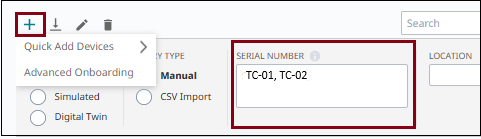
Select ![]() (Add) and then .
(Add) and then .
In the Serial Number field, enter both Tunnel Concentrator serial numbers, separated by a comma.
From the Policy drop-down, select the network policy.
Select Add Devices.
Both devices get onboarded to ExtremeCloud IQ, and are assigned to your network policy.
Network Policy Configuration and Deployment
The remaining configuration can be completed from the Network Policy configuration.
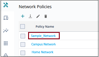
Go to and select your network policy. For example, Sample_Network.
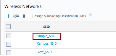
Select 2 Wireless.
Select the SSID to which you want to apply Tunnel Concentrator settings. For example, Sample_SSID.
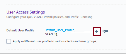
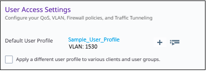
Under User Access Settings, and for the Default User Profile, select the adjacent ![]() to create a new default user profile to hold the Tunnel Concentrator settings.
to create a new default user profile to hold the Tunnel Concentrator settings.

Note
In this example, you are creating a new user profile. However, you can also select and edit an existing profile.
To assign your user profile as non-default profile, select Apply a different user profile to various clients and groups, then select or create the user profile. Next, configure assignment rules to determine when the non-default profile gets applied instead of the default profile
For the newly created user profile, configure the following settings.
Enter a Name for the new profile. For example, Sample_User_Profile.
For Connect to, select VLAN and assign a VLAN ID. For example, 1530.
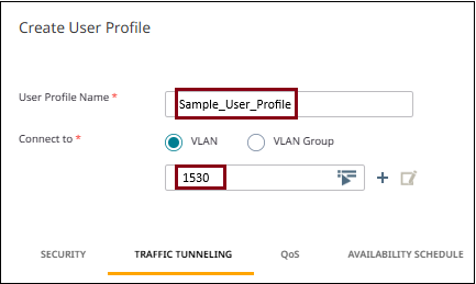
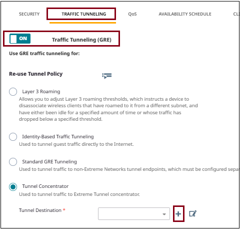
Select the Traffic Tunneling tab and toggle Traffic Tunneling (GRE) to ON.
Note
If you have an existing tunnel policy that points to a Tunnel Concentrator service, you can reuse that policy's Tunnel Concentrator settings in the user profile. Select Re-use Tunnel PolicySelect Tunnel Concentrator.
For Tunnel Destination, select ![]() to create a new Tunnel Concentrator service to act as tunnel destination for this profile.
to create a new Tunnel Concentrator service to act as tunnel destination for this profile.
In the New Tunnel Concentrator Service window, assign the following settings:
Name=Sample_TC_Service
Redundant Tunnel Concentrator
Tunnel IP Address/CIDR=10.10.10.112/24
VRRP Router ID=1
Native VLAN ID=1530
Device Tunnel Concentrator=TC-01
Tunnel Port=Port 1
VLAN ID= 15
IP Address=10.10.10.4
Bridge Port=Port 3
Device Tunnel Concentrator=TC-02
Tunnel Port=Port 1
VLAN ID=15
IP Address=10.10.10.62
Bridge Port=Port 3
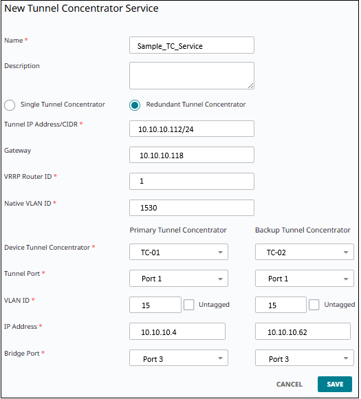
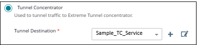
Select Save to save the new Tunnel Concentrator service.
The new Tunnel Concentrator service displays as Tunnel Destination within the User Profile configuration.
Select Save User Profile.
The new user profile with the Tunnel Concentrator settings displays as Default User Profile within the SSID configuration. The VLAN from the user profile is default VLAN for the SSID.
Select Save to save the SSID configuration.
Deploy the network policy to affected APs and Tunnel Concentrators using a delta push.