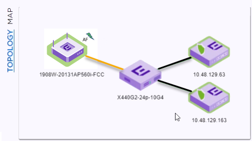
The Topology diagram displays the selected AP port connection to one or more
switches, which are connected to ExtremeCloud IQ
Controller. The diagram (shown in Topology Map representing
LLDP Port Connectivity) represents the relationship between an AP, a switch, and ExtremeCloud IQ
Controller,
displaying the link speed between the AP ports and the switch ports, and connection
status with ExtremeCloud IQ
Controller.
If the Link Layer Discovery
Protocol (LLDP) is not enabled on the switch, LLDP data is not available.
LLDP data not available
The AP reports switch port connection details to ExtremeCloud IQ
Controller. Reported
properties include the following:
AP
The AP reports the AP
Name and Power Source. Power Source values include normal and restricted
levels for the following:
AF
AT
Switch
When both LLDP (Link
Layer Discovery Protocol) and TLV (Type Length Value) advertisement are
enabled, the switch reports the Switch Port and System Name. If only the
LLDP is enabled, the switch Port Number displays. If the LLDP is not
enabled on the switch, the switch is a gray icon.
ExtremeCloud IQ
Controller
ExtremeCloud IQ
Controller reports the controller Connectivity Status and IP address.
The connection status is indicated as follows:
Green
A green lightning
icon with a green icon border indicates that the AP power level
is normal.
A
green shield on the controller indicates that an AP secure
tunnel is enabled for the AP connection to ExtremeCloud IQ
Controller.
A green line
indicates that the port speed between the AP and switch is the
maximum AP port speed. Refer to Port Speeds per Access
Point.
Yellow
A yellow
lightning icon with a yellow icon border indicates that the AP
power level is low.
A yellow line
indicates that the port speed between the AP and switch is less
than the maximum AP port speed. Refer to Port Speeds per Access
Point.
Red
A red shield on the controller indicates that an
AP secure tunnel is disabled for the AP connection to ExtremeCloud IQ
Controller.
Table 1. Port Speeds per Access
Point
AP Model
Port 1
Port 2
AP3xx
1Gb (PoE)
1Gb
AP4xx
2.5Gb (PoE)
1Gb
AP505
2.5Gb (PoE)
1Gb
AP510i/e, AP510-1i, AP560i/h
5Gb (PoE)
1Gb (PoE)
AP4000
2.5Gb (PoE)
1Gb
Note
The Topology map is not
supported on AP39xx access points.
Note
If you have configured the
selected AP on an associated floor plan, you can view the selected AP on the
floor plan map from here. Select Map to view the
selected AP on the floor plan. For more information, see Floor Plan View.