This section highlights the control panel features on the front of the C5215. See C5215 Front Control Panel Features for a description of each control.
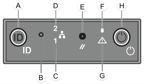
C5215 Front Control Panel Features
| Callout | Feature | Function |
|---|---|---|
| A | System ID Button w/Integrated LED | The identification buttons on the front panel can be used to locate a particular system within a rack. When one of the buttons is pushed, the blue system status indicator on the front and back blinks until one of the buttons is pushed again. |
| B | NMI Button | |
| C | Mgmt Port Activity LED | For more information, see RJ45 Port LEDs (Management Port, Data Port 1, Data Port 2). |
| D | Data Port 2 Activity LED | For more information, see RJ45 Port LEDs (Management Port, Data Port 1, Data Port 2). |
| E | System Cold Reset Button | |
| F | Drive Activity LED | The blue-colored system status indicator blinks to indicate the location of a particular system within a rack. The indicator continues to blink until one of the system identification button is pushed again. |
| G | System Status LED | The blue-colored system status indicator blinks to indicate the location of a particular system within a rack. The indicator continues to blink until one of the system identification button is pushed again. |
| H | Power Button w/Integrated LED | The power button controls the DC power supply output to the system. |
| Blinking Green - Power on with drive activity | ||
| Solid Amber - Hard drive fault has occurred |
RJ45 Port LEDs (Management Port, Data Port 1, Data Port 2)
| LED Type | LED Pattern | Status Indication |
|---|---|---|
| Network Speed (Right) | Off | 10 Mb/s |
| Amber | 1 Gb/s | |
| Green | 100 Mb/s | |
| Link Activity (Left) | Off | No link |
| Solid Green | Active link | |
| Blinking Green | Data traffic activity | |
| LED Type | LED Pattern | Status Indication |
 Print
this page
Print
this page Email this topic
 Feedback
 View PDF
 Download EPUB