C5210 Back Panel Features displays back panel features of the C5210. C5210 Back Panel Features depicts the features and functions of the C5210 back panel.
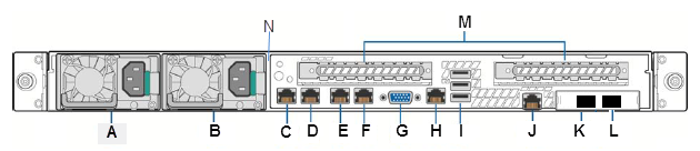
C5210 Back Panel Features
| Callout | Feature | Function |
|---|---|---|
| A | AC Power Supply 1 | AC Power Supply 1 and 2 combine to make a redundant power supply. |
| B | AC Power Supply 2 | |
| C | 1GbE RJ45 | Management port – eth0 |
| D | 1GbE RJ45 | Data port 1 – esa0 |
| E | 1GbE RJ45 | Data port 2 – esa1 |
| F | Port 4 | Not used |
| G | Video Connector | Used to see POST BIOS information during controller boot up |
| H | Serial-A Port RJ45 | Console Port – Used to get into Rescue mode. |
| I | USB Ports | Connects USB 2.0-compliant devices to the system. For more information, see the Note below. |
| J | RMM4 NIC Port | Not used, plugged |
| K | 1/10GbE SFP+ | Data port 4 – esa3 |
| L | 1/10GbE SFP+ | Data port 3 – esa2 |
| M | Expansion slots. | Not used |
| N | Chassis tab | Used for optional cable bracket. |

Note
The C5210 is equipped with 5 USB connectors — 2 on the front panel and 3 on the back panel. However, the controller is capable of supporting only one USB device at a time, regardless of what USB connector the device is connected to. If you connect a second USB device while the first is already connected, the system will return an error. Print
this page
Print
this page Email this topic
 Feedback
 View PDF
 Download EPUB