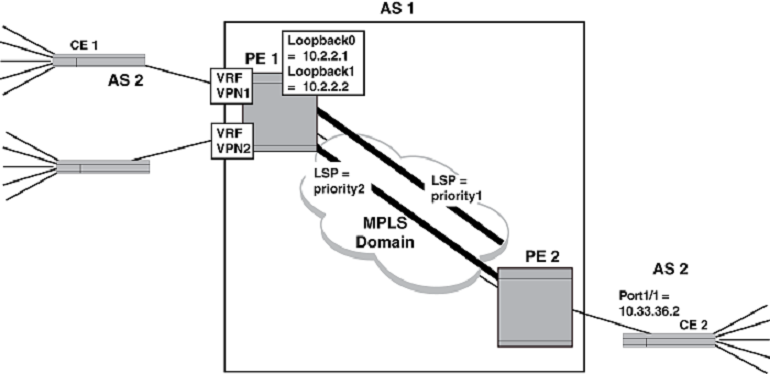
The diagram below provides an example of assigning a different LSP for each VRF on a PE. In this example, PE 1 contains two VRFs: VPN1 and VPN2. It also contains two loopback interfaces with the following IP addresses: Loopback 1 = 10.2.2.1 and Loopback 2 = 10.2.2.2. Nexthop addresses for VPN1 and VPN2 can be created separately to Loopback 1 and Loopback 2. Then, different LSPs are assigned to each of the Loopback addresses.
The following configuration example shows the elements in the PE 2 configuration required to make this example operate.
      device(config)# vrf VPN1
device(config-vrf-vpn1)# bgp next-hop loopback 1
device(config-vrf-vpn1)# exit-vrf
device(config)# vrf VPN2
device(config-vrf-vpn2)# bgp next-hop loopback 2
device(config-vrf-vpn2)# exit-vrf

device(config)# router mpls
device(config-mpls)# mpls-interface ethernet 0/1
device(config-mpls)# lsp priority1
device(config-mpls-lsp-priority1)# to 10.2.2.2
device(config-mpls-lsp-priority1)# primary-path prim-path1
device(config-mpls-lsp-priority1)# secondary-path sec-path1
device(config-mpls-lsp-priority1)# enable
device(config-mpls)# lsp priority2
device(config-mpls-lsp-priority2)# to 10.2.2.1
device(config-mpls-lsp-priority2)# primary prim-path2
device(config-mpls-lsp-priority2)# secondary sec-path2
device(config-mpls-lsp-priority2)# enable