EVPN VXLAN-L3GW functionality support is one of the several key features under the larger umbrella of IP Fabrics.
The following sections describe two features for Layer 3 routing.
Similar to the normal MAC routes that are exported and installed by EVPN BGP extensions, IP-MAC routes are also exported and installed on the remote nodes. The components of this scenario are detailed here.
BGP MAC/IP routes
This kind of route represents L3-to-L2 mapping, which is basically through ARP or ND. Static, dynamic ARP/ND entries are both exported to remote PEs and get installed as host routes. IPv4/IPv6 addresses that are configured on VE interfaces are also exported.
Upon ARP learning/gleaning/snooping on a local PE, ARP/ND information is exported to its EVPN BGP peers. The information mainly includes the following: MAC, IP/IPv6, L2-VNI, and L3-VNI. Such imported ARP/ND routes are installed or withdrawn as host routes in the hardware on the remote nodes. In the control plane they are available through the ARP suppression cache, which could be further used to reply for further ARP requests from hosts attached to the remote PE.
The packet path is as follows:
On the nondefault VRF, the ARP/ND exports can have two subscenarios, depending on whether L2-VNI is extended on that PE or not:
On the default VRF, formal host IP forwarding is done.
For multitenant scenarios using VRFs in data centers, the L3-VNI identifies a particular tenant VRF across a VXLAN-EVPN tunnel. As the name suggests, L3-VNI is used mainly for routing purposes and in short identifies the tenant VRF.
BGP IP prefix routes on VRFs are exported to the remote PE by means of EVPN (Type-5). The information mainly includes the following: Egress-PE-GW-MAC, IP/IPv6 prefix route, and L3-VNI.
Such imported IP prefix routes are imported to VRFs and are installed as VRF routes, with the VXLAN tunnel having L3-VNI as the outgoing port and remote PE-GW-MAC as the destination MAC within the inner payload L2 header.
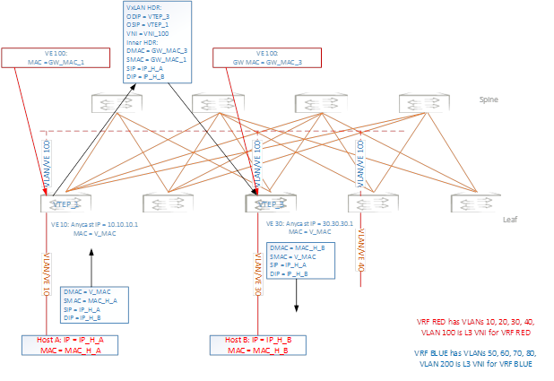
The packet path is as follows:
The following figure illustrates this topology.